HP ENVY 17-3095ca HP ENVY 17 - Maintenance and Service Guide - Page 79
Audio/USB board ZIF cable and audio/USB board cable, Power button board cable
 |
View all HP ENVY 17-3095ca manuals
Add to My Manuals
Save this manual to your list of manuals |
Page 79 highlights
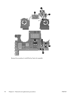
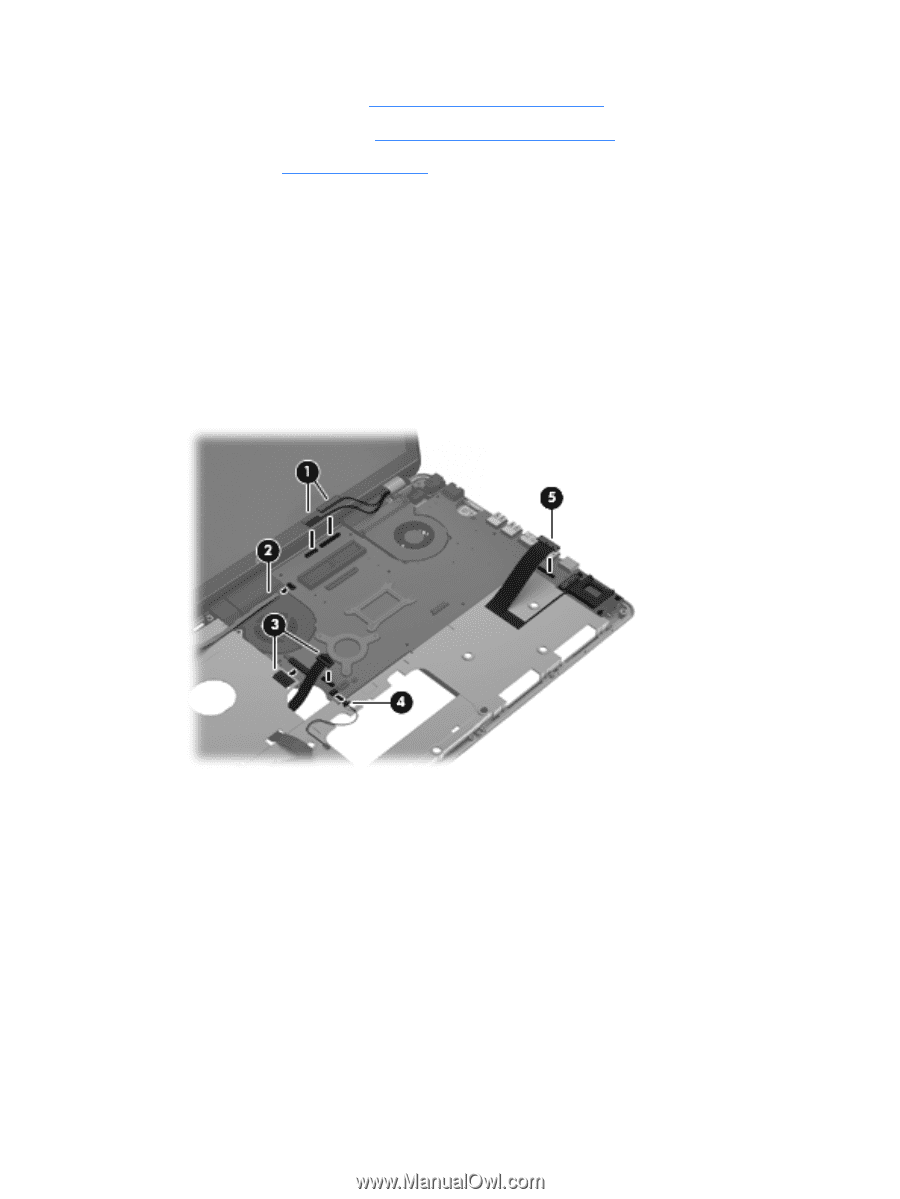
● Power connector cable (see Power connector cable on page 73) ● Fan/heat sink assembly (see Fan/heat sink assembly on page 74) ● Processor (see Processor on page 77) Remove the system board: 1. Disconnect the following cables from the system board: (1) Display panel cable and display function cable (2) Power button board cable (3) Audio/USB board ZIF cable and audio/USB board cable (4) TouchPad LED board cable (5) Card Reader board cable 2. Release the power connector (1) from the clip built into the base enclosure. ENWW Component replacement procedures 71
-
 1
1 -
2
-
3
-
4
-
5
-
6
-
7
-
8
-
9
-
10
-
11
-
12
-
13
-
14
-
15
-
16
-
17
-
18
-
19
-
20
-
21
-
22
-
23
-
24
-
25
-
26
-
27
-
28
-
29
-
30
-
31
-
32
-
33
-
34
-
35
-
36
-
37
-
38
-
39
-
40
-
41
-
42
-
43
-
44
-
45
-
46
-
47
-
48
-
49
-
50
-
51
-
52
-
53
-
54
-
55
-
56
-
57
-
58
-
59
-
60
-
61
-
62
-
63
-
64
-
65
-
66
-
67
-
68
-
69
-
70
-
71
-
72
-
73
-
 74
74 -
 75
75 -
 76
76 -
 77
77 -
 78
78 -
 79
79 -
 80
80 -
 81
81 -
 82
82 -
 83
83 -
 84
84 -
85
-
86
-
87
-
88
-
89
-
90
-
91
-
92
-
93
-
94
-
95
-
96
-
97
-
98
-
99
-
100
-
101
-
102
-
103
-
104
-
105
-
106
-
107
-
108
-
109
-
110
-
111
-
112
-
113
-
114
-
115
-
116
-
117
-
118
-
119
-
120
 |
 |
●
Power connector cable (see
Power connector cable
on page
73
)
●
Fan/heat sink assembly (see
Fan/heat sink assembly
on page
74
)
●
Processor (see
Processor
on page
77
)
Remove the system board:
1.
Disconnect the following cables from the system board:
(1)
Display panel cable and display function cable
(2)
Power button board cable
(3)
Audio/USB board ZIF cable and audio/USB board cable
(4)
TouchPad LED board cable
(5)
Card Reader board cable
2.
Release the power connector
(1)
from the clip built into the base enclosure.
ENWW
Component replacement procedures
71