HP ENVY 17-3095ca HP ENVY 17 - Maintenance and Service Guide - Page 87
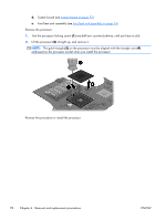
Display assembly, Remove the top cover see
 |
View all HP ENVY 17-3095ca manuals
Add to My Manuals
Save this manual to your list of manuals |
Page 87 highlights
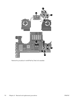
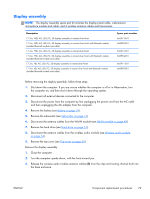
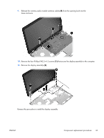
Display assembly NOTE: The display assembly spare part kit includes the display panel cable, webcamera/ microphone module and cable, and 2 wireless antenna cables and transceivers. Description 17.3-in, FHD, AG, LED, FG, 3D display assembly in natural silver finish 17.3-in, FHD, AG, LED, FG, 3D display assembly in natural silver finish with Bluetooth module (includes Bluetooth module and cable) 17.3-in, FHD, AG, LED, FG, 2D display assembly in natural silver finish 17.3-in, FHD, AG, LED, FG, 2D display assembly in natural silver finish with Bluetooth module (includes Bluetooth module and cable) 17.3-in, HD, AG, LED, FG, 2D display assembly in natural silver finish 17.3-in, HD, AG, LED, FG, 2D display assembly in natural silver finish with Bluetooth module (includes Bluetooth module and cable) Spare part number 665913-001 668995-001 665912-001 668994-001 665911-001 668993-001 Before removing the display assembly, follow these steps: 1. Shut down the computer. If you are unsure whether the computer is off or in Hibernation, turn the computer on, and then shut it down through the operating system. 2. Disconnect all external devices connected to the computer. 3. Disconnect the power from the computer by first unplugging the power cord from the AC outlet and then unplugging the AC adapter from the computer. 4. Remove the battery (see Battery on page 39). 5. Remove the subwoofer (see Subwoofer on page 41). 6. Disconnect the antenna cables from the WLAN module (see WLAN module on page 48). 7. Remove the hard drive (see Hard drive on page 51). 8. Disconnect the antenna cables from the wireless audio module (see Wireless audio module on page 54). 9. Remove the top cover (see Top cover on page 56). Remove the display assembly: 1. Close the computer. 2. Turn the computer upside down, with the front toward you. 3. Release the wireless audio module antenna cables (1) from the clips and routing channel built into the base enclosure. ENWW Component replacement procedures 79
-
 1
1 -
2
-
3
-
4
-
5
-
6
-
7
-
8
-
9
-
10
-
11
-
12
-
13
-
14
-
15
-
16
-
17
-
18
-
19
-
20
-
21
-
22
-
23
-
24
-
25
-
26
-
27
-
28
-
29
-
30
-
31
-
32
-
33
-
34
-
35
-
36
-
37
-
38
-
39
-
40
-
41
-
42
-
43
-
44
-
45
-
46
-
47
-
48
-
49
-
50
-
51
-
52
-
53
-
54
-
55
-
56
-
57
-
58
-
59
-
60
-
61
-
62
-
63
-
64
-
65
-
66
-
67
-
68
-
69
-
70
-
71
-
72
-
73
-
74
-
75
-
76
-
77
-
78
-
79
-
80
-
81
-
 82
82 -
 83
83 -
 84
84 -
 85
85 -
 86
86 -
 87
87 -
 88
88 -
 89
89 -
 90
90 -
 91
91 -
 92
92 -
93
-
94
-
95
-
96
-
97
-
98
-
99
-
100
-
101
-
102
-
103
-
104
-
105
-
106
-
107
-
108
-
109
-
110
-
111
-
112
-
113
-
114
-
115
-
116
-
117
-
118
-
119
-
120
 |
 |
