HP ENVY 17-j011nr HP ENVY 17 Notebook PC HP ENVY TouchSmart m7 Notebook PC HP - Page 100
Remove the heat sink, Remove the system board see
 |
View all HP ENVY 17-j011nr manuals
Add to My Manuals
Save this manual to your list of manuals |
Page 100 highlights
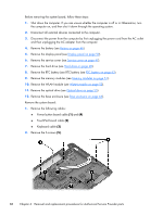
3. Disconnect the power from the computer by first unplugging the power cord from the AC outlet and then unplugging the AC adapter from the computer. 4. Remove the battery (see Battery on page 46), 5. Remove the display panel (see Display panel on page 59). 6. Remove the service cover (see Service cover on page 47). 7. Remove the hard drive (see Hard drive on page 48). 8. Remove the RTC battery (see RTC battery (see RTC battery on page 63). 9. Remove the memory modules (see Memory modules on page 51). 10. Remove the WLAN module (see WLAN module on page 52). 11. Remove the optical drive (see Optical drive on page 55). 12. Remove the base enclosure (see Base enclosure on page 64). 13. Remove the fan (see Fan on page 85). 14. Remove the system board (see System board on page 86). Remove the heat sink: ▲ Loosen the 4 captive screws in the order listed on the heat sink (1), and then remove the heat sink (2). NOTE: There is thermal paste between the heat sink and the processor. Reverse this procedure to install the heat sink. 90 Chapter 6 Removal and replacement procedures for Authorized Service Provider parts
-
 1
1 -
2
-
3
-
4
-
5
-
6
-
7
-
8
-
9
-
10
-
11
-
12
-
13
-
14
-
15
-
16
-
17
-
18
-
19
-
20
-
21
-
22
-
23
-
24
-
25
-
26
-
27
-
28
-
29
-
30
-
31
-
32
-
33
-
34
-
35
-
36
-
37
-
38
-
39
-
40
-
41
-
42
-
43
-
44
-
45
-
46
-
47
-
48
-
49
-
50
-
51
-
52
-
53
-
54
-
55
-
56
-
57
-
58
-
59
-
60
-
61
-
62
-
63
-
64
-
65
-
66
-
67
-
68
-
69
-
70
-
71
-
72
-
73
-
74
-
75
-
76
-
77
-
78
-
79
-
80
-
81
-
82
-
83
-
84
-
85
-
86
-
87
-
88
-
89
-
90
-
91
-
92
-
93
-
94
-
 95
95 -
 96
96 -
 97
97 -
 98
98 -
 99
99 -
 100
100 -
 101
101 -
 102
102 -
 103
103 -
 104
104 -
 105
105 -
106
-
107
-
108
-
109
-
110
-
111
-
112
-
113
-
114
-
115
-
116
-
117
-
118
-
119
-
120
-
121
-
122
-
123
-
124
-
125
-
126
-
127
-
128
-
129
-
130
 |
 |
