HP ENVY 17-j011nr HP ENVY 17 Notebook PC HP ENVY TouchSmart m7 Notebook PC HP - Page 106
Disengage the power connector cable, Remove the rear speakers
 |
View all HP ENVY 17-j011nr manuals
Add to My Manuals
Save this manual to your list of manuals |
Page 106 highlights
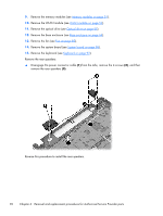
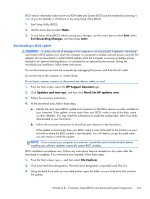
9. Remove the memory modules (see Memory modules on page 51). 10. Remove the WLAN module (see WLAN module on page 52). 11. Remove the optical drive (see Optical drive on page 55). 12. Remove the base enclosure (see Base enclosure on page 64). 13. Remove the fan (see Fan on page 85). 14. Remove the system board (see System board on page 86). 15. Remove the keyboard (see Keyboard on page 92). Remove the rear speakers: ▲ Disengage the power connector cable (1) from the tabs, remove the 4 screws (2), and then remove the rear speakers (3). Reverse this procedure to install the rear speakers. 96 Chapter 6 Removal and replacement procedures for Authorized Service Provider parts
-
 1
1 -
2
-
3
-
4
-
5
-
6
-
7
-
8
-
9
-
10
-
11
-
12
-
13
-
14
-
15
-
16
-
17
-
18
-
19
-
20
-
21
-
22
-
23
-
24
-
25
-
26
-
27
-
28
-
29
-
30
-
31
-
32
-
33
-
34
-
35
-
36
-
37
-
38
-
39
-
40
-
41
-
42
-
43
-
44
-
45
-
46
-
47
-
48
-
49
-
50
-
51
-
52
-
53
-
54
-
55
-
56
-
57
-
58
-
59
-
60
-
61
-
62
-
63
-
64
-
65
-
66
-
67
-
68
-
69
-
70
-
71
-
72
-
73
-
74
-
75
-
76
-
77
-
78
-
79
-
80
-
81
-
82
-
83
-
84
-
85
-
86
-
87
-
88
-
89
-
90
-
91
-
92
-
93
-
94
-
95
-
96
-
97
-
98
-
99
-
100
-
 101
101 -
 102
102 -
 103
103 -
 104
104 -
 105
105 -
 106
106 -
 107
107 -
 108
108 -
 109
109 -
 110
110 -
 111
111 -
112
-
113
-
114
-
115
-
116
-
117
-
118
-
119
-
120
-
121
-
122
-
123
-
124
-
125
-
126
-
127
-
128
-
129
-
130
 |
 |

9.
Remove the memory modules (see
Memory modules
on page
51
).
10.
Remove the WLAN module (see
WLAN module
on page
52
).
11.
Remove the optical drive (see
Optical drive
on page
55
).
12.
Remove the base enclosure (see
Base enclosure
on page
64
).
13.
Remove the fan (see
Fan
on page
85
).
14.
Remove the system board (see
System board
on page
86
).
15.
Remove the keyboard (see
Keyboard
on page
92
).
Remove the rear speakers:
▲
Disengage the power connector cable
(1)
from the tabs, remove the 4 screws
(2)
, and then
remove the rear speakers
(3)
.
Reverse this procedure to install the rear speakers.
96
Chapter 6
Removal and replacement procedures for Authorized Service Provider parts