HP ENVY 17-j011nr HP ENVY 17 Notebook PC HP ENVY TouchSmart m7 Notebook PC HP - Page 109
Remove the 3 Phillips PM 2.5×3.0 screws
 |
View all HP ENVY 17-j011nr manuals
Add to My Manuals
Save this manual to your list of manuals |
Page 109 highlights
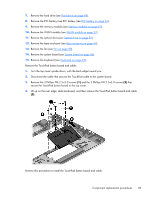
7. Remove the hard drive (see Hard drive on page 48). 8. Remove the RTC battery (see RTC battery (see RTC battery on page 63). 9. Remove the memory modules (see Memory modules on page 51). 10. Remove the WLAN module (see WLAN module on page 52). 11. Remove the optical drive (see Optical drive on page 55). 12. Remove the base enclosure (see Base enclosure on page 64). 13. Remove the fan (see Fan on page 85). 14. Remove the system board (see System board on page 86). 15. Remove the keyboard (see Keyboard on page 92). Remove the TouchPad button board and cable: 1. Turn the top cover upside down, with the back edge toward you. 2. Disconnect the cable that secures the TouchPad cable to the system board. 3. Remove the 3 Phillips PM 2.5×3.0 screws (1) and the 2 Phillips PM 2.5x3.0 screws (2) that secure the TouchPad button board to the top cover. 4. Lift up on the rear edge, slide backward, and then remove the TouchPad button board and cable (3). Reverse this procedure to install the TouchPad button board and cable. Component replacement procedures 99
-
 1
1 -
2
-
3
-
4
-
5
-
6
-
7
-
8
-
9
-
10
-
11
-
12
-
13
-
14
-
15
-
16
-
17
-
18
-
19
-
20
-
21
-
22
-
23
-
24
-
25
-
26
-
27
-
28
-
29
-
30
-
31
-
32
-
33
-
34
-
35
-
36
-
37
-
38
-
39
-
40
-
41
-
42
-
43
-
44
-
45
-
46
-
47
-
48
-
49
-
50
-
51
-
52
-
53
-
54
-
55
-
56
-
57
-
58
-
59
-
60
-
61
-
62
-
63
-
64
-
65
-
66
-
67
-
68
-
69
-
70
-
71
-
72
-
73
-
74
-
75
-
76
-
77
-
78
-
79
-
80
-
81
-
82
-
83
-
84
-
85
-
86
-
87
-
88
-
89
-
90
-
91
-
92
-
93
-
94
-
95
-
96
-
97
-
98
-
99
-
100
-
101
-
102
-
103
-
 104
104 -
 105
105 -
 106
106 -
 107
107 -
 108
108 -
 109
109 -
 110
110 -
 111
111 -
 112
112 -
 113
113 -
 114
114 -
115
-
116
-
117
-
118
-
119
-
120
-
121
-
122
-
123
-
124
-
125
-
126
-
127
-
128
-
129
-
130
 |
 |
