HP ENVY 17-j011nr HP ENVY 17 Notebook PC HP ENVY TouchSmart m7 Notebook PC HP - Page 89
USB board
 |
View all HP ENVY 17-j011nr manuals
Add to My Manuals
Save this manual to your list of manuals |
Page 89 highlights
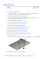
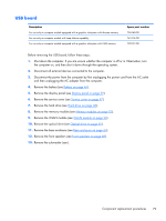
USB board Description For use only on computer models equipped with a graphics subsystem with discrete memory For use only on computer models with Leap Motion capability For use only on computer models equipped with a graphics subsystem with UMA memory Spare part number 724142-001 741074-001 720251-001 Before removing the USB board, follow these steps: 1. Shut down the computer. If you are unsure whether the computer is off or in Hibernation, turn the computer on, and then shut it down through the operating system. 2. Disconnect all external devices connected to the computer. 3. Disconnect the power from the computer by first unplugging the power cord from the AC outlet and then unplugging the AC adapter from the computer. 4. Remove the battery (see Battery on page 46). 5. Remove the display panel (see Display panel on page 59). 6. Remove the service cover (see Service cover on page 47). 7. Remove the hard drive (see Hard drive on page 48). 8. Remove the memory modules (see Memory modules on page 51). 9. Remove the WLAN module (see WLAN module on page 52). 10. Remove the optical drive (see Optical drive on page 55). 11. Remove the base enclosure (see Base enclosure on page 64). 12. Remove the front speakers (see Front speakers on page 68). 13. Remove the subwoofer (see ). Component replacement procedures 79
-
 1
1 -
2
-
3
-
4
-
5
-
6
-
7
-
8
-
9
-
10
-
11
-
12
-
13
-
14
-
15
-
16
-
17
-
18
-
19
-
20
-
21
-
22
-
23
-
24
-
25
-
26
-
27
-
28
-
29
-
30
-
31
-
32
-
33
-
34
-
35
-
36
-
37
-
38
-
39
-
40
-
41
-
42
-
43
-
44
-
45
-
46
-
47
-
48
-
49
-
50
-
51
-
52
-
53
-
54
-
55
-
56
-
57
-
58
-
59
-
60
-
61
-
62
-
63
-
64
-
65
-
66
-
67
-
68
-
69
-
70
-
71
-
72
-
73
-
74
-
75
-
76
-
77
-
78
-
79
-
80
-
81
-
82
-
83
-
 84
84 -
 85
85 -
 86
86 -
 87
87 -
 88
88 -
 89
89 -
 90
90 -
 91
91 -
 92
92 -
 93
93 -
 94
94 -
95
-
96
-
97
-
98
-
99
-
100
-
101
-
102
-
103
-
104
-
105
-
106
-
107
-
108
-
109
-
110
-
111
-
112
-
113
-
114
-
115
-
116
-
117
-
118
-
119
-
120
-
121
-
122
-
123
-
124
-
125
-
126
-
127
-
128
-
129
-
130
 |
 |
