HP ENVY 17-j011nr HP ENVY 17 Notebook PC HP ENVY TouchSmart m7 Notebook PC HP - Page 93
Remove the Leap Motion module, that secure the Leap Motion module to the top
 |
View all HP ENVY 17-j011nr manuals
Add to My Manuals
Save this manual to your list of manuals |
Page 93 highlights
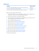
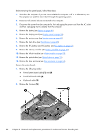
6. Remove the hard drive (see Hard drive on page 48). 7. Remove the memory modules (see Memory modules on page 51). 8. Remove the WLAN module (see WLAN module on page 52). 9. Remove the optical drive (see Optical drive on page 55). 10. Remove the base enclosure (see Base enclosure on page 64). 11. Remove the USB board (see USB board on page 79). 12. Remove the fingerprint reader module (see Fingerprint reader board on page 81). Remove the Leap Motion module: 1. Disconnect the Leap Motion module cable (1) from the system board. 2. Remove the two Phillips PM1.5×2.5 screws (2) that secure the Leap Motion module to the top cover. 3. Detach the Leap Motion module grounding shield (3) from the top cover. (The Leap Motion grounding shield is attached to the top cover with double-sided adhesive.) 4. Remove the Leap Motion module (4). Reverse this procedure to install the Leap Motion module. Component replacement procedures 83
-
 1
1 -
2
-
3
-
4
-
5
-
6
-
7
-
8
-
9
-
10
-
11
-
12
-
13
-
14
-
15
-
16
-
17
-
18
-
19
-
20
-
21
-
22
-
23
-
24
-
25
-
26
-
27
-
28
-
29
-
30
-
31
-
32
-
33
-
34
-
35
-
36
-
37
-
38
-
39
-
40
-
41
-
42
-
43
-
44
-
45
-
46
-
47
-
48
-
49
-
50
-
51
-
52
-
53
-
54
-
55
-
56
-
57
-
58
-
59
-
60
-
61
-
62
-
63
-
64
-
65
-
66
-
67
-
68
-
69
-
70
-
71
-
72
-
73
-
74
-
75
-
76
-
77
-
78
-
79
-
80
-
81
-
82
-
83
-
84
-
85
-
86
-
87
-
 88
88 -
 89
89 -
 90
90 -
 91
91 -
 92
92 -
 93
93 -
 94
94 -
 95
95 -
 96
96 -
 97
97 -
 98
98 -
99
-
100
-
101
-
102
-
103
-
104
-
105
-
106
-
107
-
108
-
109
-
110
-
111
-
112
-
113
-
114
-
115
-
116
-
117
-
118
-
119
-
120
-
121
-
122
-
123
-
124
-
125
-
126
-
127
-
128
-
129
-
130
 |
 |
