HP ENVY dv4t-5300 HP Envy dv4 Notebook PC Maintenance and Service Guide - Page 57
Top cover, instructions for these components.
 |
View all HP ENVY dv4t-5300 manuals
Add to My Manuals
Save this manual to your list of manuals |
Page 57 highlights
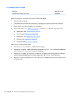
Reverse this procedure to install the keyboard. Top cover NOTE: The top cover spare part kit includes the includes TouchPad and cable. Description In black licorice finish In carmine red finish In linen white finish Spare part number 676657-001 678261-001 676658-001 Before removing the top cover, follow these steps: 1. Shut down the computer. 2. Disconnect the power from the computer by unplugging the power cord from the computer. 3. Disconnect all external devices from the computer. 4. Remove the battery (see Battery on page 34), and then remove the following components: a. Service door (see Service door on page 35) b. Hard drive (see Hard drive on page 36) c. Optical drive (see Optical drive on page 39) d. Keyboard (see Keyboard on page 46) NOTE: When replacing the top cover, be sure to remove the power button board and TouchPad button board from the defective top cover and install them on the replacement top cover. See Power button board on page 52 and TouchPad button board on page 54 for removal and replacement instructions for these components. Remove the top cover: 1. Remove the two rear rubber feet (1). The rubber feet are included in the Rubber Feet Kit, spare part number 689843-001. Component replacement procedures 49
-
 1
1 -
2
-
3
-
4
-
5
-
6
-
7
-
8
-
9
-
10
-
11
-
12
-
13
-
14
-
15
-
16
-
17
-
18
-
19
-
20
-
21
-
22
-
23
-
24
-
25
-
26
-
27
-
28
-
29
-
30
-
31
-
32
-
33
-
34
-
35
-
36
-
37
-
38
-
39
-
40
-
41
-
42
-
43
-
44
-
45
-
46
-
47
-
48
-
49
-
50
-
51
-
 52
52 -
 53
53 -
 54
54 -
 55
55 -
 56
56 -
 57
57 -
 58
58 -
 59
59 -
 60
60 -
 61
61 -
 62
62 -
63
-
64
-
65
-
66
-
67
-
68
-
69
-
70
-
71
-
72
-
73
-
74
-
75
-
76
-
77
-
78
-
79
-
80
-
81
-
82
-
83
-
84
-
85
-
86
-
87
-
88
-
89
-
90
-
91
-
92
-
93
-
94
-
95
-
96
-
97
-
98
-
99
-
100
-
101
-
102
-
103
-
104
-
105
-
106
 |
 |
