HP ENVY dv4t-5300 HP Envy dv4 Notebook PC Maintenance and Service Guide - Page 60
Power button board
 |
View all HP ENVY dv4t-5300 manuals
Add to My Manuals
Save this manual to your list of manuals |
Page 60 highlights
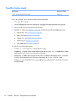
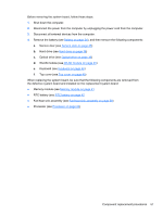
10. Use a thin plastic tool to release the top cover. Insert the tool between the top cover and base enclosure and slide the tool as shown from the following points: a. Between the VGA and HDMI connectors (1) b. Under the TouchPad area (2) CAUTION: Be careful not to damage the thin section of the base enclosure around the optical drive bay when releasing the top cover. c. Before the optical drive bay (3) d. From the rear left and right edges (4) 11. Lift the rear edge of the top cover (5). 12. Remove the top cover (6). Reverse this procedure to install the top cover. Power button board Description Power button board (includes cable) Spare part number 676651-001 Before removing the power button board, follow these steps: 1. Shut down the computer. 2. Disconnect the power from the computer by unplugging the power cord from the computer. 52 Chapter 4 Removal and replacement procedures
-
 1
1 -
2
-
3
-
4
-
5
-
6
-
7
-
8
-
9
-
10
-
11
-
12
-
13
-
14
-
15
-
16
-
17
-
18
-
19
-
20
-
21
-
22
-
23
-
24
-
25
-
26
-
27
-
28
-
29
-
30
-
31
-
32
-
33
-
34
-
35
-
36
-
37
-
38
-
39
-
40
-
41
-
42
-
43
-
44
-
45
-
46
-
47
-
48
-
49
-
50
-
51
-
52
-
53
-
54
-
 55
55 -
 56
56 -
 57
57 -
 58
58 -
 59
59 -
 60
60 -
 61
61 -
 62
62 -
 63
63 -
 64
64 -
 65
65 -
66
-
67
-
68
-
69
-
70
-
71
-
72
-
73
-
74
-
75
-
76
-
77
-
78
-
79
-
80
-
81
-
82
-
83
-
84
-
85
-
86
-
87
-
88
-
89
-
90
-
91
-
92
-
93
-
94
-
95
-
96
-
97
-
98
-
99
-
100
-
101
-
102
-
103
-
104
-
105
-
106
 |
 |
