HP ENVY dv4t-5300 HP Envy dv4 Notebook PC Maintenance and Service Guide - Page 68
Remove the Phillips M2.0×5.0 screw, Disconnect the fan cable
 |
View all HP ENVY dv4t-5300 manuals
Add to My Manuals
Save this manual to your list of manuals |
Page 68 highlights
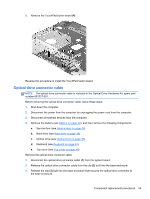
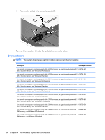
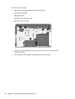
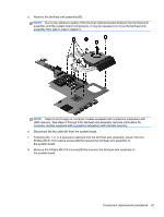
3. Disconnect all external devices from the computer. 4. Remove the battery (see Battery on page 34), and then remove the following components: a. Service door (see Service door on page 35) b. Hard drive (see Hard drive on page 36) c. Optical drive (see Optical drive on page 39) d. WLAN module (see WLAN module on page 43) e. Keyboard (see Keyboard on page 46) f. Top cover (see Top cover on page 49) g. System board (see System board on page 56) Remove the fan/heat sink assembly: 1. Turn the system board upside down, with the front toward you. NOTE: Steps 2 through 5 apply to computer models equipped with a graphics subsystem with discrete memory. See steps 6 and 9 for fan/heat sink assembly removal information for computer models equipped with a graphics subsystem with UMA memory. 2. Disconnect the fan cable (1) from the system board. 3. Following the 1, 2, 3, 4, 5, 6, 7 sequence stamped into the fan/heat sink assembly, loosen the four Phillips M2.0×10.0 captive screws (2) and the three Phillips M2.0×3.5 captive screws (3) that secure the fan/heat sink assembly to the system board. 4. Remove the Phillips M2.0×5.0 screw (4) that secures the fan/heat sink assembly to the system board. 60 Chapter 4 Removal and replacement procedures
-
 1
1 -
2
-
3
-
4
-
5
-
6
-
7
-
8
-
9
-
10
-
11
-
12
-
13
-
14
-
15
-
16
-
17
-
18
-
19
-
20
-
21
-
22
-
23
-
24
-
25
-
26
-
27
-
28
-
29
-
30
-
31
-
32
-
33
-
34
-
35
-
36
-
37
-
38
-
39
-
40
-
41
-
42
-
43
-
44
-
45
-
46
-
47
-
48
-
49
-
50
-
51
-
52
-
53
-
54
-
55
-
56
-
57
-
58
-
59
-
60
-
61
-
62
-
 63
63 -
 64
64 -
 65
65 -
 66
66 -
 67
67 -
 68
68 -
 69
69 -
 70
70 -
 71
71 -
 72
72 -
 73
73 -
74
-
75
-
76
-
77
-
78
-
79
-
80
-
81
-
82
-
83
-
84
-
85
-
86
-
87
-
88
-
89
-
90
-
91
-
92
-
93
-
94
-
95
-
96
-
97
-
98
-
99
-
100
-
101
-
102
-
103
-
104
-
105
-
106
 |
 |
