HP ENVY m6-n012dx HP ENVY m6 Notebook PC Maintenance and Service Guide - Page 60
Disconnect the the webcam/microphone module cable, from the system board.
 |
View all HP ENVY m6-n012dx manuals
Add to My Manuals
Save this manual to your list of manuals |
Page 60 highlights
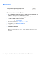
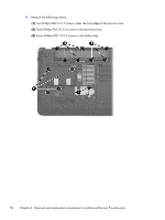
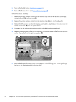
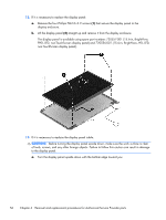
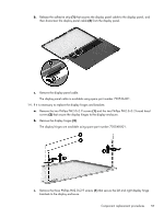
6. Remove the hard drive (see Hard drive on page 41). 7. Remove the base enclosure (see Base enclosure on page 48). Remove the display assembly: 1. Release the wireless antenna cables from the retention clips built into the left rear speaker (1), connector board (2), and top cover (3). 2. Release the wireless antenna cables from the retention clips (4) built into the subwoofer. 3. Release the ZIF connector to which the display panel cable is attached, and then disconnect the display panel cable (5) from the system board. 4. Disconnect the the webcam/microphone module cable (6) from the system board. 5. Release the display panel cable and the webcam/microphone module cable from the clips and routing channel built into the right rear speaker (7). 6. Remove the three Phillips PM2.5×4.5 screws (1) (two on the left hinge, one on the right hinge) that secure the display assembly to the top cover. 52 Chapter 6 Removal and replacement procedures for Authorized Service Provider parts
-
 1
1 -
2
-
3
-
4
-
5
-
6
-
7
-
8
-
9
-
10
-
11
-
12
-
13
-
14
-
15
-
16
-
17
-
18
-
19
-
20
-
21
-
22
-
23
-
24
-
25
-
26
-
27
-
28
-
29
-
30
-
31
-
32
-
33
-
34
-
35
-
36
-
37
-
38
-
39
-
40
-
41
-
42
-
43
-
44
-
45
-
46
-
47
-
48
-
49
-
50
-
51
-
52
-
53
-
54
-
 55
55 -
 56
56 -
 57
57 -
 58
58 -
 59
59 -
 60
60 -
 61
61 -
 62
62 -
 63
63 -
 64
64 -
 65
65 -
66
-
67
-
68
-
69
-
70
-
71
-
72
-
73
-
74
-
75
-
76
-
77
-
78
-
79
-
80
-
81
-
82
-
83
-
84
-
85
-
86
-
87
-
88
-
89
-
90
-
91
-
92
-
93
-
94
-
95
-
96
-
97
-
98
-
99
-
100
-
101
-
102
-
103
-
104
 |
 |