HP ENVY m6-n012dx HP ENVY m6 Notebook PC Maintenance and Service Guide - Page 69
Base enclosure see, Display assembly see
 |
View all HP ENVY m6-n012dx manuals
Add to My Manuals
Save this manual to your list of manuals |
Page 69 highlights
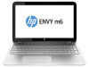
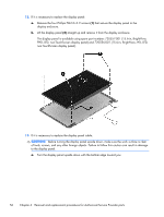
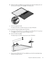
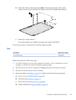
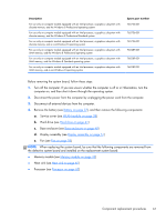
Description For use only on computer models equipped with an Intel processor, a graphics subsystem with discrete memory, and the Windows 8 Professional operating system For use only on computer models equipped with an Intel processor, a graphics subsystem with discrete memory, and the Windows 8 Professional Standard system For use only on computer models equipped with an Intel processor, a graphics subsystem with discrete memory, and a non-Windows 8 operating system For use only on computer models equipped with an Intel processor, a graphics subsystem with UMA memory, and the Windows 8 Professional operating system For use only on computer models equipped with an Intel processor, a graphics subsystem with UMA memory, and the Windows 8 Standard operating system For use only on computer models equipped with an Intel processor, a graphics subsystem with UMA memory, and a non-Windows 8 operating system Spare part number 765736-601 765736-501 765736-001 760289-601 760289-501 760289-001 Before removing the system board, follow these steps: 1. Turn off the computer. If you are unsure whether the computer is off or in Hibernation, turn the computer on, and then shut it down through the operating system. 2. Disconnect the power from the computer by unplugging the power cord from the computer. 3. Disconnect all external devices from the computer. 4. Remove the battery (see Battery on page 37), and then remove the following components: a. Service cover (see WLAN module on page 38) b. Hard drive (see Hard drive on page 41) c. Base enclosure (see Base enclosure on page 48) d. Display assembly (see Display assembly on page 51) e. Fan (see Fan on page 59) NOTE: When replacing the system board, be sure that the following components are removed from the defective system board and installed on the replacement system board: ● Memory module (see Memory module on page 43) ● Heat sink (see Heat sink on page 65) ● Processor (see Processor on page 67) Component replacement procedures 61
-
 1
1 -
2
-
3
-
4
-
5
-
6
-
7
-
8
-
9
-
10
-
11
-
12
-
13
-
14
-
15
-
16
-
17
-
18
-
19
-
20
-
21
-
22
-
23
-
24
-
25
-
26
-
27
-
28
-
29
-
30
-
31
-
32
-
33
-
34
-
35
-
36
-
37
-
38
-
39
-
40
-
41
-
42
-
43
-
44
-
45
-
46
-
47
-
48
-
49
-
50
-
51
-
52
-
53
-
54
-
55
-
56
-
57
-
58
-
59
-
60
-
61
-
62
-
63
-
 64
64 -
 65
65 -
 66
66 -
 67
67 -
 68
68 -
 69
69 -
 70
70 -
 71
71 -
 72
72 -
 73
73 -
 74
74 -
75
-
76
-
77
-
78
-
79
-
80
-
81
-
82
-
83
-
84
-
85
-
86
-
87
-
88
-
89
-
90
-
91
-
92
-
93
-
94
-
95
-
96
-
97
-
98
-
99
-
100
-
101
-
102
-
103
-
104
 |
 |