HP EliteBook 1030 Maintenance and Service Guide - Page 57
Lift the right side of the system board up at an angle, To avoid damaging or breaking the system board
 |
View all HP EliteBook 1030 manuals
Add to My Manuals
Save this manual to your list of manuals |
Page 57 highlights
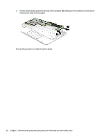
(10): RTC battery 2. Remove the WLAN antenna from the routing channel on the system board (1). 3. Remove the seven Phillips PM2.0×4.0 screws (2) that secure the system board to the computer. 4. Lift the right side of the system board up at an angle (1). CAUTION: To avoid damaging or breaking the system board, use two hands when removing the board. Do not lift up on the narrow end of the board. Component replacement procedures 49
-
 1
1 -
2
-
3
-
4
-
5
-
6
-
7
-
8
-
9
-
10
-
11
-
12
-
13
-
14
-
15
-
16
-
17
-
18
-
19
-
20
-
21
-
22
-
23
-
24
-
25
-
26
-
27
-
28
-
29
-
30
-
31
-
32
-
33
-
34
-
35
-
36
-
37
-
38
-
39
-
40
-
41
-
42
-
43
-
44
-
45
-
46
-
47
-
48
-
49
-
50
-
51
-
 52
52 -
 53
53 -
 54
54 -
 55
55 -
 56
56 -
 57
57 -
 58
58 -
 59
59 -
 60
60 -
 61
61 -
 62
62 -
63
-
64
-
65
-
66
-
67
-
68
-
69
-
70
-
71
-
72
-
73
-
74
-
75
-
76
-
77
-
78
-
79
-
80
-
81
-
82
-
83
-
84
-
85
-
86
-
87
-
88
-
89
-
90
-
91
-
92
-
93
-
94
-
95
-
96
 |
 |

(10)
: RTC battery
2.
Remove the WLAN antenna from the routing channel on the system board
(1)
.
3.
Remove the seven Phillips PM2.0×4.0 screws
(2)
that secure the system board to the computer.
4.
Lift the right side of the system board up at an angle
(1)
.
CAUTION:
To avoid damaging or breaking the system board, use two hands when removing the board.
Do not lift up on the narrow end of the board.
Component replacement procedures
49