HP Indigo 20000 CA493-00130 Rev - Page 8
Installing the charge roller rails and engage mechanisms, Tighten the 4 M6 Allen screws.
 |
View all HP Indigo 20000 manuals
Add to My Manuals
Save this manual to your list of manuals |
Page 8 highlights
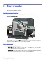
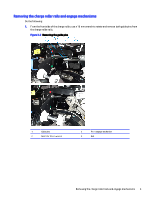
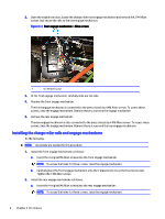
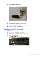
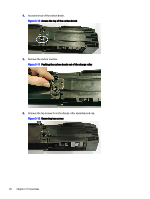
2. Open the engine rear door, locate the charge roller rear engage mechanism and remove the 2 M4 Allen screws that secure the rails to the rear engage mechanism. Figure 3-3 Rear engage mechanism - Allen screws 1 Two M4 Allen screws 3. At the front engage mechanism, carefully slide out the rails. 4. Remove the front engage mechanism. The front engage mechanism is connected to the press chassis by 4 M6 Allen screws. To access these screws, raise the engage mechanism. Remove these screws and the engage mechanism. 5. Remove the rear engage mechanism. The rear engage mechanism is also connected to the press chassis by 4 M6 Allen screws. To access these screws, raise the engage mechanism. Remove these screws and the rear engage mechanism. Installing the charge roller rails and engage mechanisms Do the following: NOTE: Two people are needed for this procedure. 1. Install the front engage mechanism as follows: a. Insert the 4 original M6 Allen screws into the front engage mechanism. NOTE: To access the holes for these screws, raise the engage mechanism. b. Carefully place the front engage mechanism onto the 2 placement pins on the front press wall. Tighten the 4 M6 Allen screws. 2. Install the rear engage mechanism as follows: a. Insert the 4 original M6 Allen screws into the rear engage mechanism. NOTE: To access the holes for these screws, raise the engage mechanism. 6 Chapter 3 Procedures
-
 1
1 -
2
-
 3
3 -
 4
4 -
 5
5 -
 6
6 -
 7
7 -
 8
8 -
 9
9 -
 10
10 -
 11
11 -
 12
12 -
 13
13 -
14
-
15
-
16
-
17
-
18
-
19
-
20
-
21
-
22
-
23
-
24
-
25
-
26
-
27
-
28
-
29
-
30
-
31
-
32
-
33
 |
 |