HP Indigo 5000 HP DesignJet 5000 Series Printer - Setup Poster - Page 2
Legs Assembly, Installing the legs onto the printer
 |
View all HP Indigo 5000 manuals
Add to My Manuals
Save this manual to your list of manuals |
Page 2 highlights
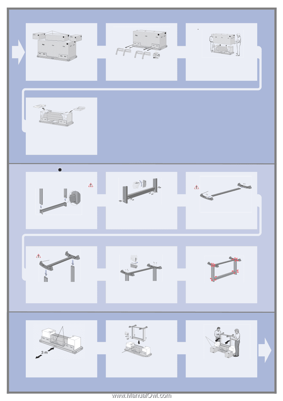
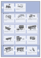
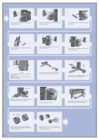
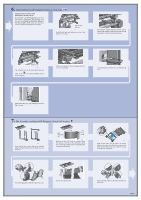
Accessory Boxes M4 st506 Remove the boxes from the top of the main printer box. st507 Remove all eight plastic handles from both sides of the box. st508 Remove the main printer box. st509 Remove the two Packing Pieces. 2. Legs Assembly When you are unpacking the legs assembly, you will see that there is ANTI-SLIP material around the wheels of the feet. DO NOT REMOVE this material yet. st511 Attach the Legs to the outside of the Cross Brace. st512 Install eight screws into the Legs as shown above. Do NOT remove anti-slip material st513 Screw the Feet into the Cross Brace. Do NOT remove anti-slip material st514 Position the Feet onto the Leg Assembly. 3. Installing the legs onto the printer Printer Handles st502 Find the handles on the rear of the printer as shown. There must be three meters from this point which is clear of obstructions. Page 2 st515 Secure the feet to the Legs with 6 screws. st522a Pull aside plastic covering Carefully pull aside the plastic covering and put the legs assembly on the Printer as shown and secure with four screws. st516 Important: Some screws may have come loose during assembly. Check that all screws are fully tightened. Orientate the boxes exactly as shown here. st523a Remove the accessories from the accessory boxes. Put the two boxes on the floor as shown and tilt the printer onto the boxes. Note: The boxes must have the polystyrene inside to support the weight of the printer.
-
 1
1 -
 2
2 -
 3
3 -
 4
4 -
 5
5 -
 6
6 -
 7
7 -
 8
8 -
9
-
10
-
11
-
12
 |
 |