HP Indigo 5000 HP DesignJet 5000 Series Printer - Setup Poster - Page 4
inch core adaptors - used
 |
View all HP Indigo 5000 manuals
Add to My Manuals
Save this manual to your list of manuals |
Page 4 highlights
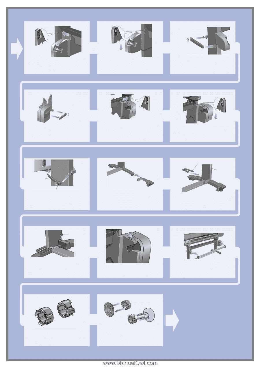
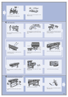
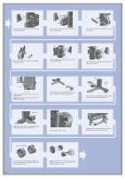
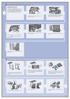
st532 Install the left-hand assembly on to the loosened screws installed earlier. st533 Pull the left-hand assembly down so that it rests securely on the screws. st534 Close the clamp and secure with the clamp screw on to the leg. st535 Release the clamp on the right-hand assembly by removing the screw. st536 Install the right-hand assembly on to the loosened screws installed earlier. st537 Pull the right-hand assembly down so that it rests securely on the screws. Clamp st538 Clamp screw Install the clamp and secure with the clamp screw as shown above. Important: Tighten all screws securing the TakeUp Reel on to the legs. st539 Install the front of the sensor assembly onto the front of the right foot assembly as shown above. Sensor clamp Right leg st540 Slide the sensor clamp hard up against the leg and then secure the sensor clamp with a screw. Sensor Cable st542 Tighten the screw to secure the clamp in place and connect the sensor cable as shown above. st545 Ensure the spindle lock is open. st546 Install the Take-Up Reel spindle into the printer by pushing firmly on each end of the spindle. 3 inch core adaptors st591 If you want to use a 3 inch (76mm) cardboard core instead of the plastic core supplied, adaptors are available with your printer. Page 4 st593 Install the adapters on to the media guides as shown. Note: These are for use with a 3 inch (76mm) cardboard core only.
-
 1
1 -
 2
2 -
 3
3 -
 4
4 -
 5
5 -
 6
6 -
 7
7 -
 8
8 -
 9
9 -
 10
10 -
11
-
12
 |
 |