HP Integrity Superdome SX2000 AD380A and AD381A PCIe 2-Port Gigabit Ethernet C - Page 20
Cable specifications, AD380A (copper), AD381A (fiber)
 |
View all HP Integrity Superdome SX2000 manuals
Add to My Manuals
Save this manual to your list of manuals |
Page 20 highlights
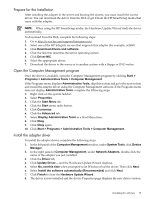
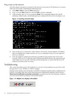
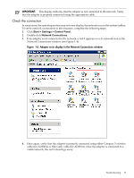
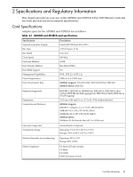
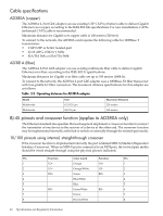
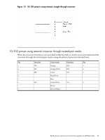
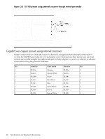
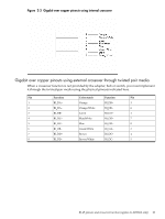
Cable specifications AD380A (copper) The AD380A 2-Port GbE adapter can use existing UTP CAT5 (or better) cable to deliver Gigabit Ethernet over copper, according to the IEEE 802.3ab specifications. For new installations, CAT5e (enhanced CAT5) cable is recommended. Maximum distance for Gigabit over copper cable is 100 meters (328 feet). To connect to the network, the AD380A card requires the following cable for 1000Base-T transmission: • CAT5 UTP or better twisted-pair • 22-26 AWG, 100Ω @ 1 MHz • EIA/TIA 568a or EIA/TIA 568b AD381A (fiber) The AD381A 2-Port GbE adapter can use existing multimode fiber cable to deliver Gigabit Ethernet over fiber, according to the IEEE 802.3z specifications. Maximum distances for Gigabit over fiber cable are up to 550 meters (1804 ft). To connect to the network, the AD381A 2-port GbE adapter uses a 1000Base-SX fiber transceiver with low-profile LC fiber connectors. The maximum distance specifications for this adapter are as follows: Table 2-2 Operating distances for AD381A adapter Mode Multimode Multimode Size 62.5/125 μm 50/125 μm Maximum Distance 220 meters 550 meters RJ-45 pinouts and crossover function (applies to AD380A only) The Ethernet standard also specifies that each segment implement a crossover function to connect the transmitter of one device to the receiver of a device at the other end. The crossover function may be implemented internally at the hub or switch or externally through the twisted-pair media. 10/100 pinouts using internal, straight-through crossover If the crossover function is implemented internally, the port is labeled MDI-X (Medium Dependent Interface-Crossover). When an MDI-X port is connected to an MDI port, the twisted pair media should be wired straight-through using the physical pinouts indicated. Pin Function Color match Function Pin 1 TD+ Orange TD+ 1 2 TD- Orange/White TD- 2 3 RD+ Green RD+ 3 4 Blue/White 4 5 Blue 5 6 RD- Green/White RD- 6 7 Brown 7 8 Brown/White 8 20 Specifications and Regulatory Information
-
 1
1 -
2
-
3
-
4
-
5
-
6
-
7
-
8
-
9
-
10
-
11
-
12
-
13
-
14
-
 15
15 -
 16
16 -
 17
17 -
 18
18 -
 19
19 -
 20
20 -
 21
21 -
 22
22 -
 23
23 -
 24
24 -
 25
25 -
26
-
27
-
28
-
29
-
30
 |
 |