HP Mini 210-3060ca HP Mini 210, HP Mini 110, and Compaq Mini CQ10 Maintenance - Page 51
Component replacement procedures, Service tag, Computer feet, Serial number label location, format
 |
View all HP Mini 210-3060ca manuals
Add to My Manuals
Save this manual to your list of manuals |
Page 51 highlights
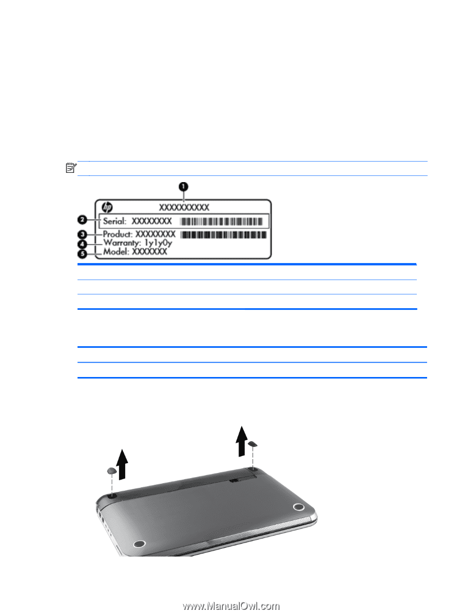
Component replacement procedures This chapter provides removal and replacement procedures. There are as many as 33 screws, in 3 different sizes, that must be removed, replaced, or loosened when servicing the computer. Make special note of each screw size and location during removal and replacement. Service tag When ordering parts or requesting information, provide the computer serial number and model number provided on the service tag, located inside the battery bay. NOTE: Serial number label location, format, and color vary on select models. (1) Product name (2) Serial number (3) Product number (4) Warranty period (5) Model description Computer feet Description Rubber Kit Spare part number 650734-001 The computer feet are adhesive-backed rubber pads. Two rubber feet are attached to the base enclosure in the locations shown in the following illustration. Component replacement procedures 43
-
 1
1 -
2
-
3
-
4
-
5
-
6
-
7
-
8
-
9
-
10
-
11
-
12
-
13
-
14
-
15
-
16
-
17
-
18
-
19
-
20
-
21
-
22
-
23
-
24
-
25
-
26
-
27
-
28
-
29
-
30
-
31
-
32
-
33
-
34
-
35
-
36
-
37
-
38
-
39
-
40
-
41
-
42
-
43
-
44
-
45
-
 46
46 -
 47
47 -
 48
48 -
 49
49 -
 50
50 -
 51
51 -
 52
52 -
 53
53 -
 54
54 -
 55
55 -
 56
56 -
57
-
58
-
59
-
60
-
61
-
62
-
63
-
64
-
65
-
66
-
67
-
68
-
69
-
70
-
71
-
72
-
73
-
74
-
75
-
76
-
77
-
78
-
79
-
80
-
81
-
82
-
83
-
84
-
85
-
86
-
87
-
88
-
89
-
90
-
91
-
92
-
93
-
94
-
95
-
96
-
97
-
98
-
99
-
100
-
101
-
102
-
103
-
104
 |
 |