HP Mini 210-3060ca HP Mini 210, HP Mini 110, and Compaq Mini CQ10 Maintenance - Page 69
Display assembly, Position the computer upside down, with the front toward you.
 |
View all HP Mini 210-3060ca manuals
Add to My Manuals
Save this manual to your list of manuals |
Page 69 highlights
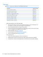
Reverse this procedure to install the TouchPad button board. Display assembly NOTE: For a complete list of display assemblies, refer to Display components on page 25. Before removing the display assembly, follow these steps: 1. Shut down the computer. If you are unsure whether the computer is off or in Hibernation, turn the computer on, and then shut it down through the operating system. 2. Disconnect all external devices connected to the computer. 3. Disconnect the power from the computer by first unplugging the power cord from the AC outlet and then unplugging the AC adapter from the computer. 4. Remove the battery (see Battery on page 44). 5. Remove the service door (see Service door on page 45). 6. Disconnect the WLAN antenna cables from the WLAN module (see WLAN module on page 46). 7. Disconnect the WWAN antenna cables from the WWAN module (see WWAN module on page 47). 8. Remove the keyboard (see Keyboard on page 53). 9. Remove the top cover (see Top cover on page 56). Remove the display assembly: 1. Close the computer. 2. Position the computer upside down, with the front toward you. 3. Remove the back corner rubber feet (1). 4. Remove the two Phillips M2.0x5.0 screws (2), one beneath each rubber foot. 5. Remove the plastic rear corner covers (3). NOTE: The rear corner covers are included in the Plastics Kit, spare part number 652308-001. Component replacement procedures 61
-
 1
1 -
2
-
3
-
4
-
5
-
6
-
7
-
8
-
9
-
10
-
11
-
12
-
13
-
14
-
15
-
16
-
17
-
18
-
19
-
20
-
21
-
22
-
23
-
24
-
25
-
26
-
27
-
28
-
29
-
30
-
31
-
32
-
33
-
34
-
35
-
36
-
37
-
38
-
39
-
40
-
41
-
42
-
43
-
44
-
45
-
46
-
47
-
48
-
49
-
50
-
51
-
52
-
53
-
54
-
55
-
56
-
57
-
58
-
59
-
60
-
61
-
62
-
63
-
 64
64 -
 65
65 -
 66
66 -
 67
67 -
 68
68 -
 69
69 -
 70
70 -
 71
71 -
 72
72 -
 73
73 -
 74
74 -
75
-
76
-
77
-
78
-
79
-
80
-
81
-
82
-
83
-
84
-
85
-
86
-
87
-
88
-
89
-
90
-
91
-
92
-
93
-
94
-
95
-
96
-
97
-
98
-
99
-
100
-
101
-
102
-
103
-
104
 |
 |
