HP Mini 210-3060ca HP Mini 210, HP Mini 110, and Compaq Mini CQ10 Maintenance - Page 80
and processor, thoroughly removed and replaced each time the heat sink is removed.
 |
View all HP Mini 210-3060ca manuals
Add to My Manuals
Save this manual to your list of manuals |
Page 80 highlights
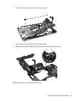
2. Remove the heat sink (2) by lifting it straight up from the system board. NOTE: Due to the adhesive quality of the thermal material between the heat sink and system board components, you may need to move the heat sink from side to side to detach it from the system board. NOTE: Thermal paste located on the surfaces of the heat sink (1) and processor (2) must be thoroughly removed and replaced each time the heat sink is removed. Reverse this procedure to install the Fan and sink. 72 Chapter 4 Removal and replacement procedures
-
 1
1 -
2
-
3
-
4
-
5
-
6
-
7
-
8
-
9
-
10
-
11
-
12
-
13
-
14
-
15
-
16
-
17
-
18
-
19
-
20
-
21
-
22
-
23
-
24
-
25
-
26
-
27
-
28
-
29
-
30
-
31
-
32
-
33
-
34
-
35
-
36
-
37
-
38
-
39
-
40
-
41
-
42
-
43
-
44
-
45
-
46
-
47
-
48
-
49
-
50
-
51
-
52
-
53
-
54
-
55
-
56
-
57
-
58
-
59
-
60
-
61
-
62
-
63
-
64
-
65
-
66
-
67
-
68
-
69
-
70
-
71
-
72
-
73
-
74
-
 75
75 -
 76
76 -
 77
77 -
 78
78 -
 79
79 -
 80
80 -
 81
81 -
 82
82 -
 83
83 -
 84
84 -
 85
85 -
86
-
87
-
88
-
89
-
90
-
91
-
92
-
93
-
94
-
95
-
96
-
97
-
98
-
99
-
100
-
101
-
102
-
103
-
104
 |
 |

2.
Remove the heat sink
(2)
by lifting it straight up from the system board.
NOTE:
Due to the adhesive quality of the thermal material between the heat sink and system
board components, you may need to move the heat sink from side to side to detach it from the
system board.
NOTE:
Thermal paste located on the surfaces of the heat sink
(1)
and processor
(2)
must be
thoroughly removed and replaced each time the heat sink is removed.
Reverse this procedure to install the Fan and sink.
72
Chapter 4
Removal and replacement procedures