HP Mini 311-1028TU HP Pavilion dm1 HP Mini 311 Compaq Mini 311 - Maintenance a - Page 78
System board, When replacing the system board
 |
View all HP Mini 311-1028TU manuals
Add to My Manuals
Save this manual to your list of manuals |
Page 78 highlights
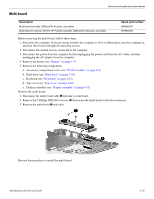
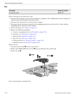
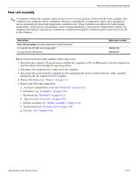
Removal and replacement procedures System board Description Spare part number System board (includes processor, 1024-MB base memory, and replacement thermal material): Includes Intel Atom N280 1.66-GHz processor, 512-KB Level 2 cache, 667-MHz front-side bus (FSB) for use with the HP Mini and Compaq Mini 580000-001 Includes Intel Atom N270 1.6-GHz processor, 512-KB Level 2 cache, 533-MHz front-side bus (FSB) 579999-001 for use with the HP Mini and Compaq Mini Includes Intel Pentium 1.3-GHz processor, 2048-KB Level 2 cache, 800-MHz FSB for use with HP 581751-001 Pavilion Includes Intel Pentium 1.2-GHz processor, 1024-KB Level 2 cache, 800-MHz FSB for use with the 581750-001 HP Pavilion Before removing the system board, follow these steps: 1. Shut down the computer. If you are unsure whether the computer is off or in Hibernation, turn the computer on, and then shut it down through the operating system. 2. Disconnect all external devices connected to the computer. 3. Disconnect the power from the computer by first unplugging the power cord from the AC outlet, and then unplugging the AC adapter from the computer. 4. Remove the battery (see "Battery" on page 4-7). 5. Remove the following components: a. Accessory compartment cover (see "WLAN module" on page 4-9) b. Hard drive (see "Hard drive" on page 4-18) c. Keyboard (see "Keyboard" on page 4-21) d. Top cover (see "Top cover" on page 4-24) e. Display assembly (see "Display assembly" on page 4-31) When replacing the system board, be sure that the following additional components are removed from the defective system board and installed on the replacement system board: ■ SIM (see "SIM" on page 4-8) ■ WLAN module (see "WLAN module" on page 4-9) ■ RTC battery (see "RTC battery" on page 4-15) ■ Expansion memory module (see "Expansion memory module" on page 4-16) ■ WWAN module (see "WWAN module" on page 4-13) ■ Power connector (see "Power connector" on page 4-41) ■ Fan (see "Fan" on page 4-42) ■ Heat sink (see "Heat sink assembly" on page 4-43) 4-38 Maintenance and Service Guide
-
 1
1 -
2
-
3
-
4
-
5
-
6
-
7
-
8
-
9
-
10
-
11
-
12
-
13
-
14
-
15
-
16
-
17
-
18
-
19
-
20
-
21
-
22
-
23
-
24
-
25
-
26
-
27
-
28
-
29
-
30
-
31
-
32
-
33
-
34
-
35
-
36
-
37
-
38
-
39
-
40
-
41
-
42
-
43
-
44
-
45
-
46
-
47
-
48
-
49
-
50
-
51
-
52
-
53
-
54
-
55
-
56
-
57
-
58
-
59
-
60
-
61
-
62
-
63
-
64
-
65
-
66
-
67
-
68
-
69
-
70
-
71
-
72
-
 73
73 -
 74
74 -
 75
75 -
 76
76 -
 77
77 -
 78
78 -
 79
79 -
 80
80 -
 81
81 -
 82
82 -
 83
83 -
84
-
85
-
86
-
87
-
88
-
89
-
90
-
91
-
92
-
93
-
94
-
95
-
96
-
97
-
98
-
99
-
100
-
101
-
102
-
103
-
104
-
105
-
106
-
107
-
108
-
109
-
110
-
111
-
112
-
113
-
114
-
115
-
116
-
117
-
118
-
119
-
120
-
121
-
122
-
123
-
124
-
125
-
126
-
127
-
128
-
129
-
130
-
131
-
132
-
133
-
134
-
135
-
136
-
137
-
138
 |
 |
