HP Mini 311-1028TU HP Pavilion dm1 HP Mini 311 Compaq Mini 311 - Maintenance a - Page 84
Step 2 applies to HP Mini and Compaq Mini computer models. See Step 3 for HP Pavilion computer models.
 |
View all HP Mini 311-1028TU manuals
Add to My Manuals
Save this manual to your list of manuals |
Page 84 highlights
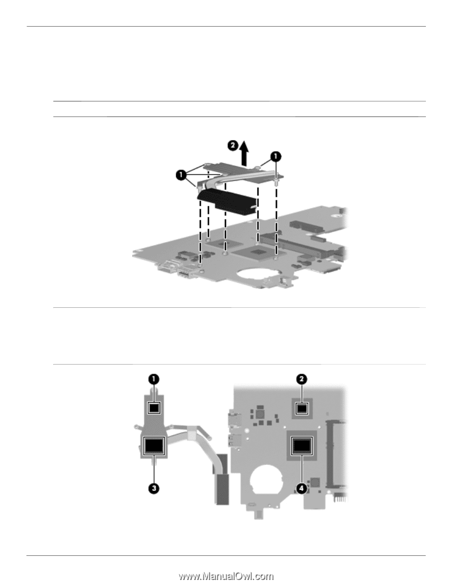
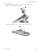
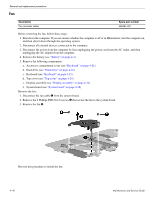
Removal and replacement procedures Remove the heat sink assembly: 1. Following the 1, 2, 3, 4, 5 sequence stamped into the heat sink assembly, loosen the 5 Phillips PM2.0×6.0 captive screws 1 that secure the fan and heat sink assembly to the system board. ✎ Due to the adhesive quality of the thermal material located between the heat sink and system board components, it may be necessary to move the heat sink from side to side to detach it. ✎ Step 2 applies to HP Mini and Compaq Mini computer models. See Step 3 for HP Pavilion computer models. 2. Remove the heat sink assembly 2. ✎ The thermal material must be thoroughly cleaned from the surfaces of the heat sink and the system board each time the fan and heat sink are removed: ■ Thermal paste is used on the processor 1 and the heat sink section 2 that services it. ■ Thermal pads are used on the MCP79 chip 3 and the heat sink section 4 that services it. Replacement thermal material is included with all system board and heat sink assembly spare part kits. 4-44 Maintenance and Service Guide
-
 1
1 -
2
-
3
-
4
-
5
-
6
-
7
-
8
-
9
-
10
-
11
-
12
-
13
-
14
-
15
-
16
-
17
-
18
-
19
-
20
-
21
-
22
-
23
-
24
-
25
-
26
-
27
-
28
-
29
-
30
-
31
-
32
-
33
-
34
-
35
-
36
-
37
-
38
-
39
-
40
-
41
-
42
-
43
-
44
-
45
-
46
-
47
-
48
-
49
-
50
-
51
-
52
-
53
-
54
-
55
-
56
-
57
-
58
-
59
-
60
-
61
-
62
-
63
-
64
-
65
-
66
-
67
-
68
-
69
-
70
-
71
-
72
-
73
-
74
-
75
-
76
-
77
-
78
-
 79
79 -
 80
80 -
 81
81 -
 82
82 -
 83
83 -
 84
84 -
 85
85 -
 86
86 -
 87
87 -
 88
88 -
 89
89 -
90
-
91
-
92
-
93
-
94
-
95
-
96
-
97
-
98
-
99
-
100
-
101
-
102
-
103
-
104
-
105
-
106
-
107
-
108
-
109
-
110
-
111
-
112
-
113
-
114
-
115
-
116
-
117
-
118
-
119
-
120
-
121
-
122
-
123
-
124
-
125
-
126
-
127
-
128
-
129
-
130
-
131
-
132
-
133
-
134
-
135
-
136
-
137
-
138
 |
 |