HP NetServer AA 4000 HP Netserver AA 6200 Solutions Release Notes v4.0 SP1 - Page 15
Cabling for Staging Purposes in Long Distance SplitSite Installations
 |
View all HP NetServer AA 4000 manuals
Add to My Manuals
Save this manual to your list of manuals |
Page 15 highlights
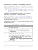
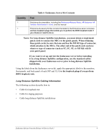
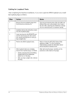
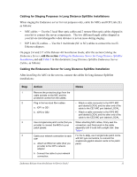
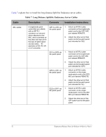
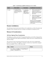
Cabling for Staging Purposes in Long Distance SplitSite Installations When staging the Endurance server for test purposes only, cable the MICs and IOP Link (IL) as follows: • MIC cables - Use the 2 local fiber optic cables and 2 remote fiber optic cables shipped in your kit to connect the server components. The two different length cables shipped in your kit are interchangeable when distance is not an issue during staging. • IOP Link (IL) cables - Use the 2 multimode (SC to SC) cables to connect the two IL Ethernet adapters. On pages 2-6 and 2-7 of the Release 4.0 Installation Guide, after the section Cabling the Endurance Server, add the section Cabling the Endurance Server for Long Distance SplitSite Installation, and add Table 7 in this document, Long Distance SplitSite Endurance Server Cables, as follows: Cabling the Endurance Server for Long Distance SplitSite Installation After Installing the MICs in the servers, connect the cables for long distance SplitSite installations: Step 1 2 3 4 Action Notes Remove the protective plugs from the cable sockets on the MIC and the protective covers from the cables. Plug in the two local fiber cables: a. IOP1 to CE1 b. IOP2 to CE2 Use 4 singlemode patch cords (that you provide) to connect the MICs to your patch panels. Cable your network connection to each IOP: a. Attach an Ethernet cable (that you provide) to the IOP's network adapter. b. Connect the cable to your network connection. • Attach a cable connector to the IOP1 MIC port labeled LOCAL and the other end of the cable to the CE1 MIC port labeled LOCAL. • Attach a cable connector to the IOP2 MIC port labeled LOCAL and the other end of the cable to the CE2 MIC port labeled LOCAL. When attaching MIC cables, firmly seat the connectors, and firmly push in the cable assembly until it locks with a slight click. See Table 7. For the IL only, use 2 singlemode patch cords, with SC type connectors, to connect the singlemode gigabit network cards to the patch panel. Endurance Release Notes for Release 4.0 Service Pack 1 11
-
 1
1 -
2
-
3
-
4
-
5
-
6
-
7
-
8
-
9
-
 10
10 -
 11
11 -
 12
12 -
 13
13 -
 14
14 -
 15
15 -
 16
16 -
 17
17 -
 18
18 -
 19
19 -
 20
20 -
21
-
22
-
23
-
24
 |
 |