HP NetServer AA 4000 HP Netserver AA 6200 Solutions Release Notes v4.0 SP1 - Page 16
Table 7, Long Distance SplitSite Endurance Server Cables, Cable, Description, Connects
 |
View all HP NetServer AA 4000 manuals
Add to My Manuals
Save this manual to your list of manuals |
Page 16 highlights
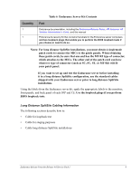
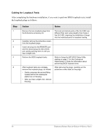
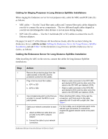
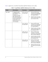
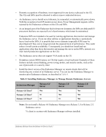
Table 7 explains how to install the long distance SplitSite Endurance server cables. Table 7 Long Distance SplitSite Endurance Server Cables Cable Description Connects Installation Instructions MIC cables 4 singlemode patch cords (that you obtain), with an MT-RJ connector on one end, which attaches to the MIC, and a connector at the other end that will fit the type of patch panel you are using - for example, an SC, FC, ST, or LC connector. IOP1 to CE2 via the patch panel CE1 to IOP2 via the patch panel IOP2 to CE1 via the patch panel CE2 to IOP1 via the patch panel 1. Attach an MT-RJ cable connector on the singlemode patch cord to the IOP1 MIC port labeled REMOTE. 2. Attach the other end of that patch cord to the patch panel port intended for CE2. 1. Attach an MT-RJ cable connector on the singlemode patch cord to the CE1 MIC port labeled REMOTE. 2. Attach the other end of that patch cord to the patch panel port intended for IOP2. 1. Attach an MT-RJ cable connector on the single mode patch cord to the IOP2 MIC port labeled REMOTE. 2. Attach the other end of that patch cord to the patch panel port intended for CE1. 1. Attach an MT-RJ cable connector on the single mode patch cord to the CE2 MIC port labeled REMOTE. 2. Attach the other end of the IOP1 patch cord to the patch panel. 12 Endurance Release Notes for Release 4.0 Service Pack 1
-
 1
1 -
2
-
3
-
4
-
5
-
6
-
7
-
8
-
9
-
10
-
 11
11 -
 12
12 -
 13
13 -
 14
14 -
 15
15 -
 16
16 -
 17
17 -
 18
18 -
 19
19 -
 20
20 -
 21
21 -
22
-
23
-
24
 |
 |