HP Pavilion 13-a010dx HP Pavilion x360 Convertible PC Maintenance and Service - Page 56
Remove the display assembly, Release the display TouchScreen cable from the routing clip
 |
View all HP Pavilion 13-a010dx manuals
Add to My Manuals
Save this manual to your list of manuals |
Page 56 highlights
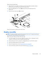
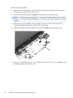
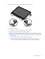
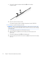
Remove the display assembly: 1. Release the ZIF connector (1) to which the display panel cable is attached, and then disconnect the display panel cable from the system board. 2. Disconnect the WLAN antenna cables (2) from the terminals on the WLAN module. NOTE: The WLAN antenna cable labeled "1" connects to the WLAN module "Main" terminal labeled "1". The WLAN antenna cable labeled "2" connects to the WLAN module "Aux" terminal labeled "2". 3. Release the ZIF connector (3) to which the display TouchScreen cable is attached, and then disconnect the display TouchScreen cable from the system board. 4. Release the display TouchScreen cable from the routing clip (4) built into the bottom cover. 5. Remove the three Phillips PM2.5×5.7 screws (1) and the Phillips PM2.5×3.3 screw (2) that secure the display assembly to the bottom cover. 48 Chapter 5 Removal and replacement procedures
-
 1
1 -
2
-
3
-
4
-
5
-
6
-
7
-
8
-
9
-
10
-
11
-
12
-
13
-
14
-
15
-
16
-
17
-
18
-
19
-
20
-
21
-
22
-
23
-
24
-
25
-
26
-
27
-
28
-
29
-
30
-
31
-
32
-
33
-
34
-
35
-
36
-
37
-
38
-
39
-
40
-
41
-
42
-
43
-
44
-
45
-
46
-
47
-
48
-
49
-
50
-
 51
51 -
 52
52 -
 53
53 -
 54
54 -
 55
55 -
 56
56 -
 57
57 -
 58
58 -
 59
59 -
 60
60 -
 61
61 -
62
-
63
-
64
-
65
-
66
-
67
-
68
-
69
-
70
-
71
-
72
-
73
-
74
-
75
-
76
-
77
-
78
-
79
-
80
-
81
-
82
-
83
-
84
-
85
-
86
 |
 |
