HP Pavilion 17-f200 Pavilion 17 Notebook PC Pavilion 15 Notebook PC Maintenanc - Page 54
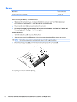
that secure the optical drive bracket to the optical drive., Remove the two screws
 |
View all HP Pavilion 17-f200 manuals
Add to My Manuals
Save this manual to your list of manuals |
Page 54 highlights
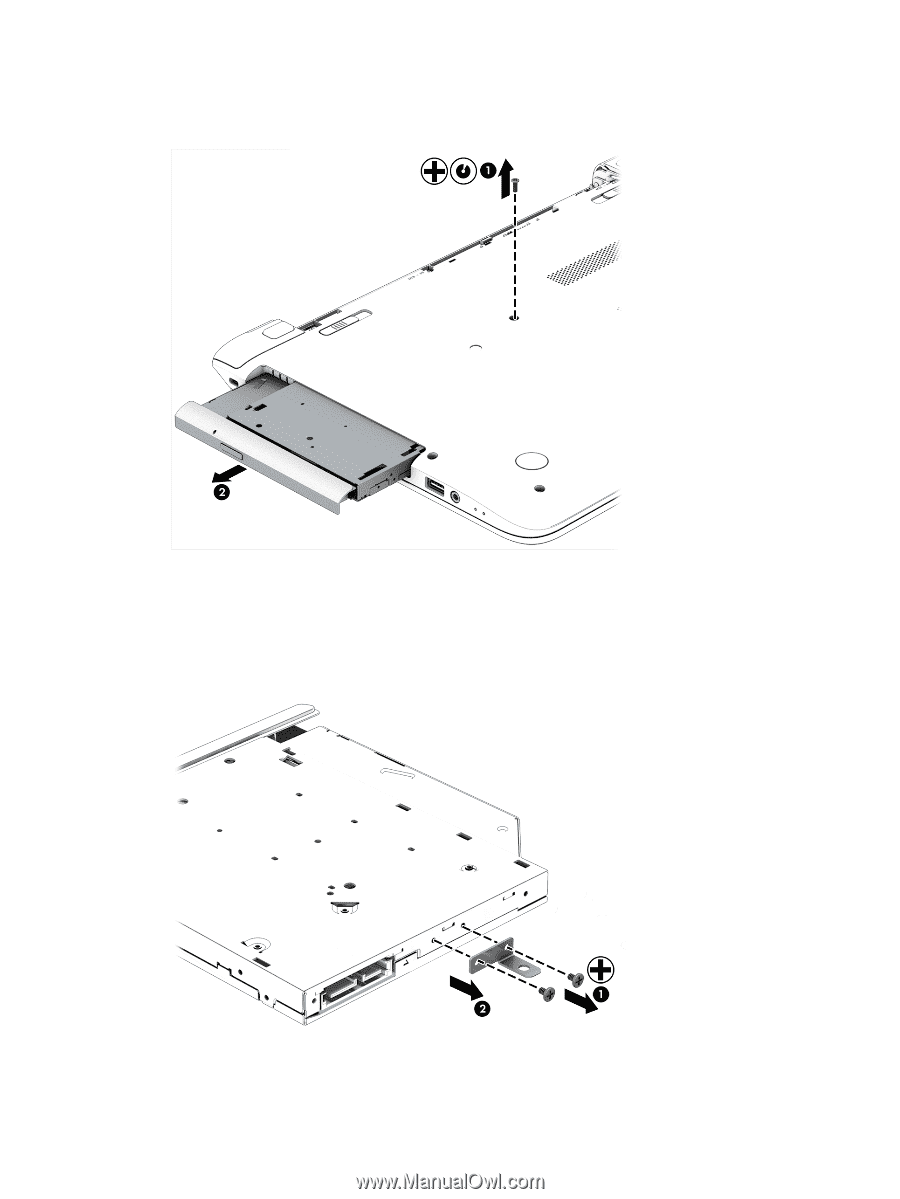
1. Remove the screw (1) that secures the optical drive to the computer. 2. Use a flat tool to press on the optical drive bracket tab (2) to release the optical drive. 3. Remove the optical drive from the computer. 4. If it is necessary to replace the optical drive bracket, position the optical drive with the rear panel toward you. 5. Remove the two screws (1) that secure the optical drive bracket to the optical drive. 6. Remove the optical drive bracket (2). Reverse this procedure to reassemble and install the optical drive. 44 Chapter 5 Removal and replacement procedures for Customer Self-Repair parts
-
 1
1 -
2
-
3
-
4
-
5
-
6
-
7
-
8
-
9
-
10
-
11
-
12
-
13
-
14
-
15
-
16
-
17
-
18
-
19
-
20
-
21
-
22
-
23
-
24
-
25
-
26
-
27
-
28
-
29
-
30
-
31
-
32
-
33
-
34
-
35
-
36
-
37
-
38
-
39
-
40
-
41
-
42
-
43
-
44
-
45
-
46
-
47
-
48
-
 49
49 -
 50
50 -
 51
51 -
 52
52 -
 53
53 -
 54
54 -
 55
55 -
 56
56 -
 57
57 -
 58
58 -
 59
59 -
60
-
61
-
62
-
63
-
64
-
65
-
66
-
67
-
68
-
69
-
70
-
71
-
72
-
73
-
74
-
75
-
76
-
77
-
78
-
79
-
80
-
81
-
82
-
83
-
84
-
85
-
86
-
87
-
88
-
89
-
90
-
91
-
92
-
93
-
94
-
95
-
96
-
97
-
98
-
99
-
100
-
101
-
102
-
103
-
104
-
105
-
106
-
107
-
108
-
109
-
110
-
111
-
112
-
113
-
114
-
115
-
116
-
117
-
118
-
119
-
120
-
121
-
122
-
123
-
124
-
125
-
126
-
127
-
128
 |
 |
1.
Remove the screw
(1)
that secures the optical drive to the computer.
2.
Use a flat tool to press on the optical drive bracket tab
(2)
to release the optical drive.
3.
Remove the optical drive from the computer.
4.
If it is necessary to replace the optical drive bracket, position the optical drive with the rear panel
toward you.
5.
Remove the two screws
(1)
that secure the optical drive bracket to the optical drive.
6.
Remove the optical drive bracket
(2)
.
Reverse this procedure to reassemble and install the optical drive.
44
Chapter 5
Removal and replacement procedures for Customer Self-Repair parts