HP Pavilion 17-f200 Pavilion 17 Notebook PC Pavilion 15 Notebook PC Maintenanc - Page 76
Optical drive connector
 |
View all HP Pavilion 17-f200 manuals
Add to My Manuals
Save this manual to your list of manuals |
Page 76 highlights
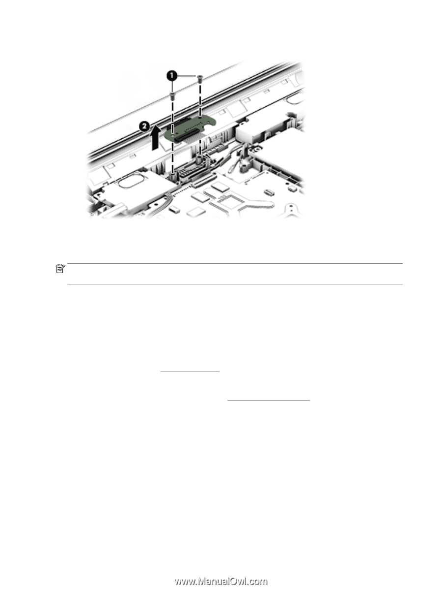
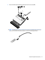
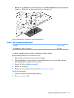
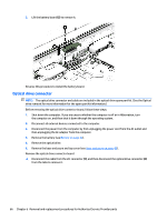
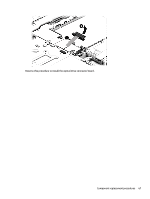
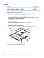
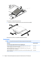
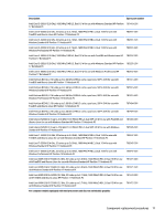
3. Lift the battery board (2) to remove it. Reverse this procedure to install the battery board. Optical drive connector NOTE: The optical drive connector and cable are included in the optical drive spare part kit. (See the Optical drive removal for more information for the spare part kit information.) Before removing the optical drive connector board, follow these steps: 1. Shut down the computer. If you are unsure whether the computer is off or in Hibernation, turn the computer on, and then shut it down through the operating system. 2. Disconnect all external devices connected to the computer. 3. Disconnect the power from the computer by first unplugging the power cord from the AC outlet and then unplugging the AC adapter from the computer. 4. Remove the battery (see Battery on page 42). 5. Remove the optical drive. 6. Remove the base enclosure and top cover (see Base enclosure on page 46). Remove the optical drive connector board: ▲ Disconnect the cable from the ZIF connector (1), and then disconnect the optical drive connector (2) from the tabs to remove it. 66 Chapter 6 Removal and replacement procedures for Authorized Service Provider parts
-
 1
1 -
2
-
3
-
4
-
5
-
6
-
7
-
8
-
9
-
10
-
11
-
12
-
13
-
14
-
15
-
16
-
17
-
18
-
19
-
20
-
21
-
22
-
23
-
24
-
25
-
26
-
27
-
28
-
29
-
30
-
31
-
32
-
33
-
34
-
35
-
36
-
37
-
38
-
39
-
40
-
41
-
42
-
43
-
44
-
45
-
46
-
47
-
48
-
49
-
50
-
51
-
52
-
53
-
54
-
55
-
56
-
57
-
58
-
59
-
60
-
61
-
62
-
63
-
64
-
65
-
66
-
67
-
68
-
69
-
70
-
 71
71 -
 72
72 -
 73
73 -
 74
74 -
 75
75 -
 76
76 -
 77
77 -
 78
78 -
 79
79 -
 80
80 -
 81
81 -
82
-
83
-
84
-
85
-
86
-
87
-
88
-
89
-
90
-
91
-
92
-
93
-
94
-
95
-
96
-
97
-
98
-
99
-
100
-
101
-
102
-
103
-
104
-
105
-
106
-
107
-
108
-
109
-
110
-
111
-
112
-
113
-
114
-
115
-
116
-
117
-
118
-
119
-
120
-
121
-
122
-
123
-
124
-
125
-
126
-
127
-
128
 |
 |