HP Pavilion 17-f200 Pavilion 17 Notebook PC Pavilion 15 Notebook PC Maintenanc - Page 87
procedure is to remove the power connector cover if did not remove it when removing the display panel.
 |
View all HP Pavilion 17-f200 manuals
Add to My Manuals
Save this manual to your list of manuals |
Page 87 highlights
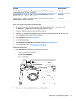
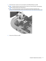
3. Remove the power connector cover by removing the screw(s) (1) and lifting the cover (2). NOTE: The power connector cover has two screws, however, the screw on the left is removed during the base enclosure and top cover removal process. NOTE: You will remove the power connector after you have removed the system board. This procedure is to remove the power connector cover if did not remove it when removing the display panel. 4. Remove the six Phillips screws (1). Component replacement procedures 77
-
 1
1 -
2
-
3
-
4
-
5
-
6
-
7
-
8
-
9
-
10
-
11
-
12
-
13
-
14
-
15
-
16
-
17
-
18
-
19
-
20
-
21
-
22
-
23
-
24
-
25
-
26
-
27
-
28
-
29
-
30
-
31
-
32
-
33
-
34
-
35
-
36
-
37
-
38
-
39
-
40
-
41
-
42
-
43
-
44
-
45
-
46
-
47
-
48
-
49
-
50
-
51
-
52
-
53
-
54
-
55
-
56
-
57
-
58
-
59
-
60
-
61
-
62
-
63
-
64
-
65
-
66
-
67
-
68
-
69
-
70
-
71
-
72
-
73
-
74
-
75
-
76
-
77
-
78
-
79
-
80
-
81
-
 82
82 -
 83
83 -
 84
84 -
 85
85 -
 86
86 -
 87
87 -
 88
88 -
 89
89 -
 90
90 -
 91
91 -
 92
92 -
93
-
94
-
95
-
96
-
97
-
98
-
99
-
100
-
101
-
102
-
103
-
104
-
105
-
106
-
107
-
108
-
109
-
110
-
111
-
112
-
113
-
114
-
115
-
116
-
117
-
118
-
119
-
120
-
121
-
122
-
123
-
124
-
125
-
126
-
127
-
128
 |
 |
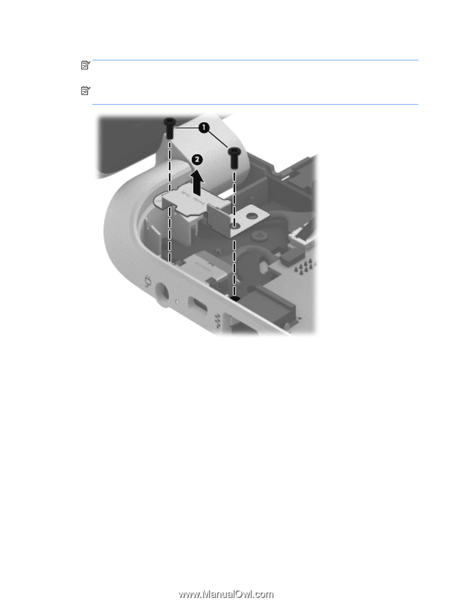
3.
Remove the power connector cover by removing the screw(s)
(1)
and lifting the cover
(2)
.
NOTE:
The power connector cover has two screws, however, the screw on the left is removed during
the base enclosure and top cover removal process.
NOTE:
You will remove the power connector after you have removed the system board. This
procedure is to remove the power connector cover if did not remove it when removing the display panel.
4.
Remove the six Phillips screws
(1)
.
Component replacement procedures
77