HP Pavilion dv4-3100 HP Pavilion dv4 Entertainment PC - Maintenance and Servic - Page 82
Fan/heat sink assembly
 |
View all HP Pavilion dv4-3100 manuals
Add to My Manuals
Save this manual to your list of manuals |
Page 82 highlights
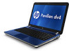
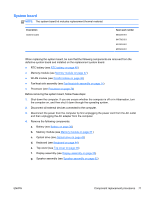
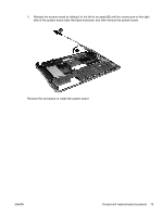
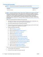
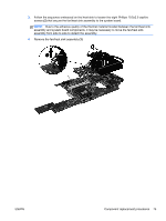
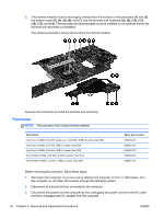
Fan/heat sink assembly NOTE: The fan/heat sink assembly kit includes replacement thermal material. Description Fan/heat sink assembly Spare part number 644515-001 NOTE: To properly ventilate the computer, allow at least a 7.6-cm (3-inch) clearance on the right side and rear panel of the computer. The computer uses an electric fan for ventilation. The fan is controlled by a temperature sensor and is designed to turn on automatically when high temperature conditions exist. These conditions are affected by high external temperatures, system power consumption, power management/battery conservation configurations, battery fast charging, and software requirements. Exhaust air is displaced through the ventilation grill located on the left side of the computer. Before removing the fan/heat sink assembly, follow these steps: 1. Shut down the computer. If you are unsure whether the computer is off or in Hibernation, turn the computer on, and then shut it down through the operating system. 2. Disconnect all external devices connected to the computer. 3. Disconnect the power from the computer by first unplugging the power cord from the AC outlet and then unplugging the AC adapter from the computer. 4. Remove the following components: a. Battery (see Battery on page 36) b. Memory module (see Memory module on page 37 ) c. Optical drive (see Optical drive on page 42) d. Keyboard (see Keyboard on page 44) e. Top cover (see Top cover on page 49) f. Display assembly (see Display assembly on page 55) g. Speaker assembly (see Speaker assembly on page 62) h. Audio/USB 2.0 board (see Audio/USB 2.0 board on page 63) i. TouchPad LED board (see TouchPad LED board on page 65) j. Power connector (see Power connector on page 69) k. System board (see System board on page 71) l. USB 3.0 board (see USB 3.0 board* on page 64) Remove the fan/heat assembly (fan/heat sink appearance may vary): 1. Turn the system board upside down. 2. Disconnect the fan cable from the system board (1). 74 Chapter 4 Removal and replacement procedures ENWW
-
 1
1 -
2
-
3
-
4
-
5
-
6
-
7
-
8
-
9
-
10
-
11
-
12
-
13
-
14
-
15
-
16
-
17
-
18
-
19
-
20
-
21
-
22
-
23
-
24
-
25
-
26
-
27
-
28
-
29
-
30
-
31
-
32
-
33
-
34
-
35
-
36
-
37
-
38
-
39
-
40
-
41
-
42
-
43
-
44
-
45
-
46
-
47
-
48
-
49
-
50
-
51
-
52
-
53
-
54
-
55
-
56
-
57
-
58
-
59
-
60
-
61
-
62
-
63
-
64
-
65
-
66
-
67
-
68
-
69
-
70
-
71
-
72
-
73
-
74
-
75
-
76
-
 77
77 -
 78
78 -
 79
79 -
 80
80 -
 81
81 -
 82
82 -
 83
83 -
 84
84 -
 85
85 -
 86
86 -
 87
87 -
88
-
89
-
90
-
91
-
92
-
93
-
94
-
95
-
96
-
97
-
98
-
99
-
100
-
101
-
102
-
103
-
104
-
105
-
106
-
107
-
108
-
109
-
110
-
111
-
112
-
113
-
114
-
115
-
116
-
117
-
118
-
119
-
120
 |
 |