HP Pavilion dv4-3100 HP Pavilion dv4 Entertainment PC - Maintenance and Servic - Page 85
one-half turn counterclockwise until you hear a click., Lift the processor
 |
View all HP Pavilion dv4-3100 manuals
Add to My Manuals
Save this manual to your list of manuals |
Page 85 highlights
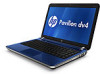
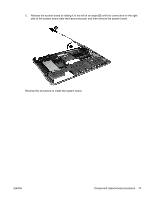
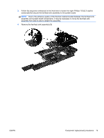
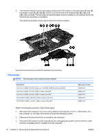
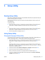
4. Remove the battery (see Battery on page 36). 5. Remove the following components: a. Battery (see Battery on page 36) b. Memory module (see Memory module on page 37 ) c. Optical drive (see Optical drive on page 42) d. Keyboard (see Keyboard on page 44) e. Top cover (see Top cover on page 49) f. Display assembly (see Display assembly on page 55) g. Speaker assembly (see Speaker assembly on page 62) h. Audio/USB 2.0 board (see Audio/USB 2.0 board on page 63) i. TouchPad LED board (see TouchPad LED board on page 65) j. Power connector (see Power connector on page 69) k. System board (see System board on page 71) l. USB 3.0 board (see USB 3.0 board* on page 64) Remove the processor: 1. Turn the processor locking screw (1) one-half turn counterclockwise until you hear a click. 2. Lift the processor (2) straight up and remove it. NOTE: The gold triangle (3) on the processor must be aligned with the triangle icon (4) embossed on the processor socket when you install the processor. Reverse this procedure to install the processor. ENWW Component replacement procedures 77
-
 1
1 -
2
-
3
-
4
-
5
-
6
-
7
-
8
-
9
-
10
-
11
-
12
-
13
-
14
-
15
-
16
-
17
-
18
-
19
-
20
-
21
-
22
-
23
-
24
-
25
-
26
-
27
-
28
-
29
-
30
-
31
-
32
-
33
-
34
-
35
-
36
-
37
-
38
-
39
-
40
-
41
-
42
-
43
-
44
-
45
-
46
-
47
-
48
-
49
-
50
-
51
-
52
-
53
-
54
-
55
-
56
-
57
-
58
-
59
-
60
-
61
-
62
-
63
-
64
-
65
-
66
-
67
-
68
-
69
-
70
-
71
-
72
-
73
-
74
-
75
-
76
-
77
-
78
-
79
-
 80
80 -
 81
81 -
 82
82 -
 83
83 -
 84
84 -
 85
85 -
 86
86 -
 87
87 -
 88
88 -
 89
89 -
 90
90 -
91
-
92
-
93
-
94
-
95
-
96
-
97
-
98
-
99
-
100
-
101
-
102
-
103
-
104
-
105
-
106
-
107
-
108
-
109
-
110
-
111
-
112
-
113
-
114
-
115
-
116
-
117
-
118
-
119
-
120
 |
 |