HP Pavilion dv6-1200 HP Pavilion dv6 Entertainment PC - Maintenance and Servic - Page 103
and capacitors and their contacts
 |
View all HP Pavilion dv6-1200 manuals
Add to My Manuals
Save this manual to your list of manuals |
Page 103 highlights
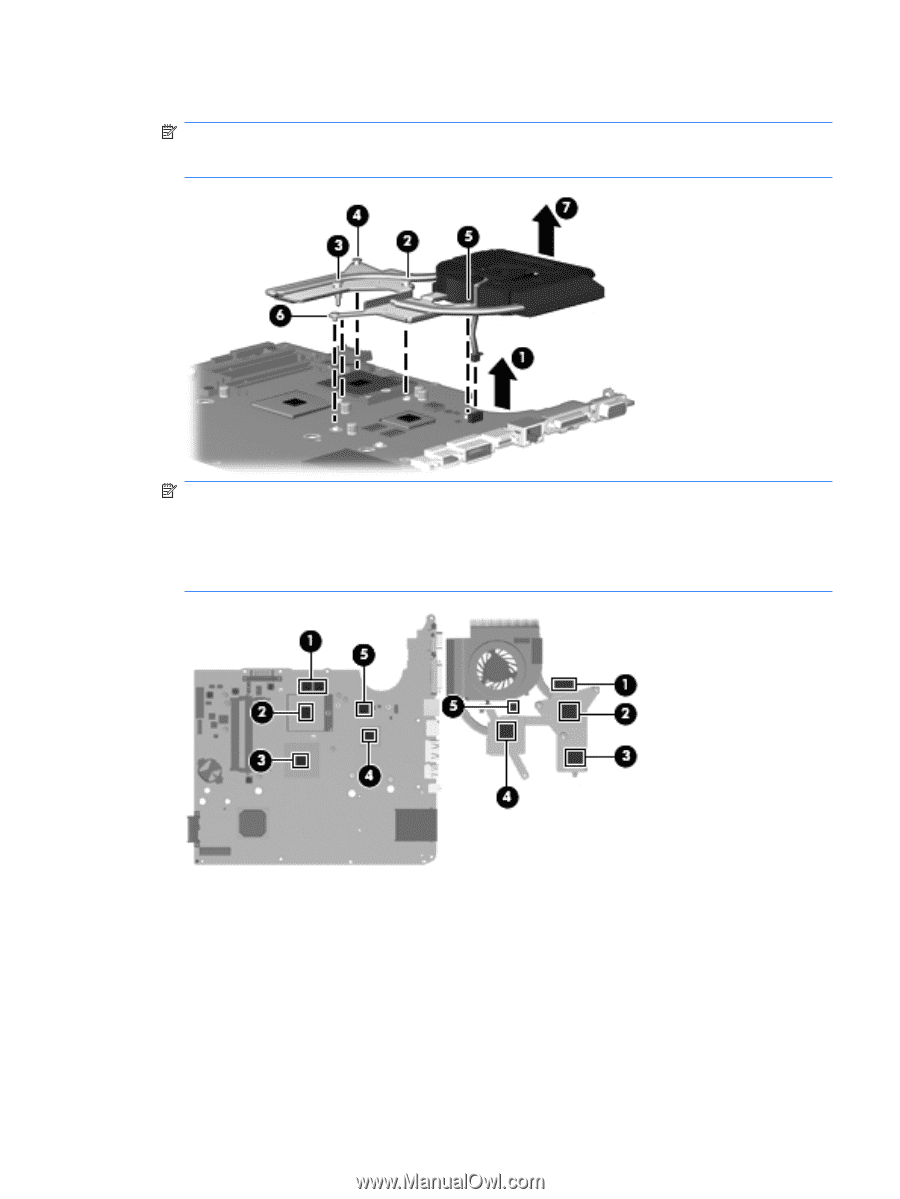
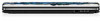
10. Remove the fan/heat sink assembly (7). NOTE: Due to the adhesive quality of the thermal material located between the fan/heat sink assembly and system board components, it may be necessary to move the fan/heat sink assembly from side to side to detach the assembly. NOTE: The thermal material must be thoroughly cleaned from the surfaces of the fan/heat sink assembly and the system board each time the fan/heat sink assembly is removed. Thermal paste is applied to the fan/heat sink assembly to correspond with components on the system board as follows: capacitors and their contacts (1) the processor and contact (2), the graphics subsystem chip and contact (3), and capacitors and their contacts (4) and (5). Replacement thermal material is included with all fan/heat sink assembly, system board, and processor spare part kits. Reverse this procedure to install the fan/heat sink assembly. Component replacement procedures 95
-
 1
1 -
2
-
3
-
4
-
5
-
6
-
7
-
8
-
9
-
10
-
11
-
12
-
13
-
14
-
15
-
16
-
17
-
18
-
19
-
20
-
21
-
22
-
23
-
24
-
25
-
26
-
27
-
28
-
29
-
30
-
31
-
32
-
33
-
34
-
35
-
36
-
37
-
38
-
39
-
40
-
41
-
42
-
43
-
44
-
45
-
46
-
47
-
48
-
49
-
50
-
51
-
52
-
53
-
54
-
55
-
56
-
57
-
58
-
59
-
60
-
61
-
62
-
63
-
64
-
65
-
66
-
67
-
68
-
69
-
70
-
71
-
72
-
73
-
74
-
75
-
76
-
77
-
78
-
79
-
80
-
81
-
82
-
83
-
84
-
85
-
86
-
87
-
88
-
89
-
90
-
91
-
92
-
93
-
94
-
95
-
96
-
97
-
 98
98 -
 99
99 -
 100
100 -
 101
101 -
 102
102 -
 103
103 -
 104
104 -
 105
105 -
 106
106 -
 107
107 -
 108
108 -
109
-
110
-
111
-
112
-
113
-
114
-
115
-
116
-
117
-
118
-
119
-
120
-
121
-
122
-
123
-
124
-
125
-
126
-
127
-
128
-
129
-
130
-
131
-
132
-
133
-
134
-
135
-
136
-
137
-
138
-
139
-
140
-
141
-
142
-
143
-
144
-
145
-
146
-
147
-
148
-
149
-
150
-
151
-
152
-
153
-
154
-
155
-
156
-
157
-
158
-
159
-
160
-
161
-
162
-
163
-
164
-
165
-
166
 |
 |