HP Pavilion dv6-1200 HP Pavilion dv6 Entertainment PC - Maintenance and Servic - Page 82
Two Phillips PM2.5×6.5 screws.
 |
View all HP Pavilion dv6-1200 manuals
Add to My Manuals
Save this manual to your list of manuals |
Page 82 highlights
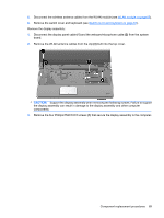
27. If you need to remove the horizontal bracket from the vertical hinge brackets, remove the two Phillips PM2.0×5.0 screws (1) that connect the brackets together, and then disconnect the brackets (2). NOTE: Steps 28 through 38 provide display assembly internal component removal information for computers equipped with BrightView display assemblies. See steps 5 through 27 for display assembly internal component removal information for computers equipped with AntiGlare display assemblies. NOTE: See Webcam/microphone moduleon page 49 for webcam/microphone module replacement instructions for computers equipped with BrightView display assemblies. 28. If it is necessary to replace the display bezel or any of the display assembly internal components, remove the following screw covers and screws: (1) Two Mylar screw covers on the display bezel bottom edge. The display rubber screw covers are included in the Display Rubber Kit, spare part number 512361-001. (2) Two Phillips PM2.5×6.5 screws. 29. Flex the inside edges of the top edge (1), the left and right sides (2), and the bottom edge of the display bezel (3) until the bezel disengages from the display enclosure. 74 Chapter 4 Removal and replacement procedures
-
 1
1 -
2
-
3
-
4
-
5
-
6
-
7
-
8
-
9
-
10
-
11
-
12
-
13
-
14
-
15
-
16
-
17
-
18
-
19
-
20
-
21
-
22
-
23
-
24
-
25
-
26
-
27
-
28
-
29
-
30
-
31
-
32
-
33
-
34
-
35
-
36
-
37
-
38
-
39
-
40
-
41
-
42
-
43
-
44
-
45
-
46
-
47
-
48
-
49
-
50
-
51
-
52
-
53
-
54
-
55
-
56
-
57
-
58
-
59
-
60
-
61
-
62
-
63
-
64
-
65
-
66
-
67
-
68
-
69
-
70
-
71
-
72
-
73
-
74
-
75
-
76
-
 77
77 -
 78
78 -
 79
79 -
 80
80 -
 81
81 -
 82
82 -
 83
83 -
 84
84 -
 85
85 -
 86
86 -
 87
87 -
88
-
89
-
90
-
91
-
92
-
93
-
94
-
95
-
96
-
97
-
98
-
99
-
100
-
101
-
102
-
103
-
104
-
105
-
106
-
107
-
108
-
109
-
110
-
111
-
112
-
113
-
114
-
115
-
116
-
117
-
118
-
119
-
120
-
121
-
122
-
123
-
124
-
125
-
126
-
127
-
128
-
129
-
130
-
131
-
132
-
133
-
134
-
135
-
136
-
137
-
138
-
139
-
140
-
141
-
142
-
143
-
144
-
145
-
146
-
147
-
148
-
149
-
150
-
151
-
152
-
153
-
154
-
155
-
156
-
157
-
158
-
159
-
160
-
161
-
162
-
163
-
164
-
165
-
166
 |
 |
