HP Pavilion dv6-1200 HP Pavilion dv6 Entertainment PC - Maintenance and Servic - Page 77
CAUTION, the display assembly can result in damage to the display assembly and other computer
 |
View all HP Pavilion dv6-1200 manuals
Add to My Manuals
Save this manual to your list of manuals |
Page 77 highlights
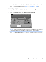
5. Disconnect the wireless antenna cables from the WLAN module (see WLAN module on page 60). 6. Remove the switch cover and keyboard (see Switch cover and keyboard on page 63). Remove the display assembly: 1. Disconnect the display panel cable (1) and the webcam/microphone cable (2) from the system board. 2. Remove the WLAN antenna cables from the clip (3) built into the top cover. CAUTION: Support the display assembly when removing the following screws. Failure to support the display assembly can result in damage to the display assembly and other computer components. 3. Remove the four Phillips PM2.5×6.5 screws (1) that secure the display assembly to the computer. Component replacement procedures 69
-
 1
1 -
2
-
3
-
4
-
5
-
6
-
7
-
8
-
9
-
10
-
11
-
12
-
13
-
14
-
15
-
16
-
17
-
18
-
19
-
20
-
21
-
22
-
23
-
24
-
25
-
26
-
27
-
28
-
29
-
30
-
31
-
32
-
33
-
34
-
35
-
36
-
37
-
38
-
39
-
40
-
41
-
42
-
43
-
44
-
45
-
46
-
47
-
48
-
49
-
50
-
51
-
52
-
53
-
54
-
55
-
56
-
57
-
58
-
59
-
60
-
61
-
62
-
63
-
64
-
65
-
66
-
67
-
68
-
69
-
70
-
71
-
 72
72 -
 73
73 -
 74
74 -
 75
75 -
 76
76 -
 77
77 -
 78
78 -
 79
79 -
 80
80 -
 81
81 -
 82
82 -
83
-
84
-
85
-
86
-
87
-
88
-
89
-
90
-
91
-
92
-
93
-
94
-
95
-
96
-
97
-
98
-
99
-
100
-
101
-
102
-
103
-
104
-
105
-
106
-
107
-
108
-
109
-
110
-
111
-
112
-
113
-
114
-
115
-
116
-
117
-
118
-
119
-
120
-
121
-
122
-
123
-
124
-
125
-
126
-
127
-
128
-
129
-
130
-
131
-
132
-
133
-
134
-
135
-
136
-
137
-
138
-
139
-
140
-
141
-
142
-
143
-
144
-
145
-
146
-
147
-
148
-
149
-
150
-
151
-
152
-
153
-
154
-
155
-
156
-
157
-
158
-
159
-
160
-
161
-
162
-
163
-
164
-
165
-
166
 |
 |

5.
Disconnect the wireless antenna cables from the WLAN module (see
WLAN module
on page
60
).
6.
Remove the switch cover and keyboard (see
Switch cover and keyboard
on page
63
).
Remove the display assembly:
1.
Disconnect the display panel cable
(1)
and the webcam/microphone cable
(2)
from the system
board.
2.
Remove the WLAN antenna cables from the clip
(3)
built into the top cover.
CAUTION:
Support the display assembly when removing the following screws. Failure to support
the display assembly can result in damage to the display assembly and other computer
components.
3.
Remove the four Phillips PM2.5×6.5 screws
(1)
that secure the display assembly to the computer.
Component replacement procedures
69