HP Pavilion dv6-1200 HP Pavilion dv6 Entertainment PC - Maintenance and Servic - Page 97
of the system board until it rests at an angle., Lift the right side
 |
View all HP Pavilion dv6-1200 manuals
Add to My Manuals
Save this manual to your list of manuals |
Page 97 highlights
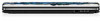
2. Disconnect the following cables from the system board: (2) Audio/infrared board cable NOTE: The audio/infrared board cable connects to a LIF connector on the system board. (3) USB board cable NOTE: The USB board cable connects to a LIF connector on the system board. (4) Power connector cable 3. Remove the Phillips PM2.5×7.0 screw (1) that secures the system board to the base enclosure. 4. Lift the right side (2) of the system board until it rests at an angle. 5. Remove the system board (3) by sliding it up and to the right at an angle. Reverse this procedure to install the system board. Component replacement procedures 89
-
 1
1 -
2
-
3
-
4
-
5
-
6
-
7
-
8
-
9
-
10
-
11
-
12
-
13
-
14
-
15
-
16
-
17
-
18
-
19
-
20
-
21
-
22
-
23
-
24
-
25
-
26
-
27
-
28
-
29
-
30
-
31
-
32
-
33
-
34
-
35
-
36
-
37
-
38
-
39
-
40
-
41
-
42
-
43
-
44
-
45
-
46
-
47
-
48
-
49
-
50
-
51
-
52
-
53
-
54
-
55
-
56
-
57
-
58
-
59
-
60
-
61
-
62
-
63
-
64
-
65
-
66
-
67
-
68
-
69
-
70
-
71
-
72
-
73
-
74
-
75
-
76
-
77
-
78
-
79
-
80
-
81
-
82
-
83
-
84
-
85
-
86
-
87
-
88
-
89
-
90
-
91
-
 92
92 -
 93
93 -
 94
94 -
 95
95 -
 96
96 -
 97
97 -
 98
98 -
 99
99 -
 100
100 -
 101
101 -
 102
102 -
103
-
104
-
105
-
106
-
107
-
108
-
109
-
110
-
111
-
112
-
113
-
114
-
115
-
116
-
117
-
118
-
119
-
120
-
121
-
122
-
123
-
124
-
125
-
126
-
127
-
128
-
129
-
130
-
131
-
132
-
133
-
134
-
135
-
136
-
137
-
138
-
139
-
140
-
141
-
142
-
143
-
144
-
145
-
146
-
147
-
148
-
149
-
150
-
151
-
152
-
153
-
154
-
155
-
156
-
157
-
158
-
159
-
160
-
161
-
162
-
163
-
164
-
165
-
166
 |
 |

2.
Disconnect the following cables from the system board:
(2)
Audio/infrared board cable
NOTE:
The audio/infrared board cable connects to a LIF connector on the system board.
(3)
USB board cable
NOTE:
The USB board cable connects to a LIF connector on the system board.
(4)
Power connector cable
3.
Remove the Phillips PM2.5×7.0 screw
(1)
that secures the system board to the base enclosure.
4.
Lift the right side
(2)
of the system board until it rests at an angle.
5.
Remove the system board
(3)
by sliding it up and to the right at an angle.
Reverse this procedure to install the system board.
Component replacement procedures
89