HP Pavilion dv6-1200 HP Pavilion dv6 Entertainment PC - Maintenance and Servic - Page 79
Remove the display enclosure. The display enclosure is available using spare part number
 |
View all HP Pavilion dv6-1200 manuals
Add to My Manuals
Save this manual to your list of manuals |
Page 79 highlights
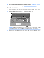
9. Disconnect the display logo cable (3) from the display panel cable. 10. Remove the WLAN antenna cables and the webcam cable (4) from the left hinge. NOTE: You may have to flex the display hinge cover to remove the WLAN cables. 11. If it is necessary to replace the display inverter, remove the four Phillips PM2.5×5.0 screws (1) that secure the display inverter cover to the display bezel. The display inverter cover is available using spare part number 533464-001. 12. Remove the display inverter cover (2) by lifting it straight up. NOTE: You must remove the display inverter cover to free the antenna cables. 13. Remove the display enclosure. The display enclosure is available using spare part number 517861-001 for white computers, and 518774-001 for black computers, and includes the display logo LED board and the wireless antenna transceivers and cables. 14. If it is necessary to replace the webcam/microphone module, remove the PM2.0x3.0 screw (1) that secures the webcam/microphone module to the display. Component replacement procedures 71
-
 1
1 -
2
-
3
-
4
-
5
-
6
-
7
-
8
-
9
-
10
-
11
-
12
-
13
-
14
-
15
-
16
-
17
-
18
-
19
-
20
-
21
-
22
-
23
-
24
-
25
-
26
-
27
-
28
-
29
-
30
-
31
-
32
-
33
-
34
-
35
-
36
-
37
-
38
-
39
-
40
-
41
-
42
-
43
-
44
-
45
-
46
-
47
-
48
-
49
-
50
-
51
-
52
-
53
-
54
-
55
-
56
-
57
-
58
-
59
-
60
-
61
-
62
-
63
-
64
-
65
-
66
-
67
-
68
-
69
-
70
-
71
-
72
-
73
-
 74
74 -
 75
75 -
 76
76 -
 77
77 -
 78
78 -
 79
79 -
 80
80 -
 81
81 -
 82
82 -
 83
83 -
 84
84 -
85
-
86
-
87
-
88
-
89
-
90
-
91
-
92
-
93
-
94
-
95
-
96
-
97
-
98
-
99
-
100
-
101
-
102
-
103
-
104
-
105
-
106
-
107
-
108
-
109
-
110
-
111
-
112
-
113
-
114
-
115
-
116
-
117
-
118
-
119
-
120
-
121
-
122
-
123
-
124
-
125
-
126
-
127
-
128
-
129
-
130
-
131
-
132
-
133
-
134
-
135
-
136
-
137
-
138
-
139
-
140
-
141
-
142
-
143
-
144
-
145
-
146
-
147
-
148
-
149
-
150
-
151
-
152
-
153
-
154
-
155
-
156
-
157
-
158
-
159
-
160
-
161
-
162
-
163
-
164
-
165
-
166
 |
 |
