HP Presario 1600 Presario Select 1200 and 1600 Series Maintenance and Service - Page 44
Home
 |
View all HP Presario 1600 manuals
Add to My Manuals
Save this manual to your list of manuals |
Page 44 highlights
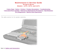
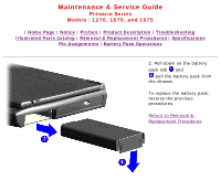
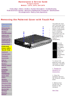
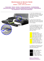
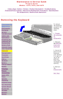
Maintenance & Service Guide Presario Series Models : 1270, 1670, and 1675 | Home Page | Notice | Preface | Product Description | Troubleshooting Illustrated Parts Catalog | Removal & Replacement Procedures | Specifications Pin Assignments | Battery Pack Operations 4. Turn the computer over (right side up), pull forward on the display latches to release and open the display assembly. 5. Lift up front end of the palmrest cover with touch pad and remove it from the groove in the chassis. 6. Tilt the palmrest cover with touch pad, allowing it to rest on top of the keyboard, and disconnect the flex cable from the LIF connector on the palmrest cover. CAUTION: When replacing the palmrest cover with touch pad, ensure that the cable is fully inserted into the LIF connector on the system board. If the metal end should come in contact with the keyboard, damage may occur to the computer. To replace the palmrest cover with touch pad, reverse the previous procedures. When replacing the palm rest cover NOTE: ensure the cable properly routed is through the slot on the Upper CPU cover. Return to Removal & Replacement Procedures
-
 1
1 -
2
-
3
-
4
-
5
-
6
-
7
-
8
-
9
-
10
-
11
-
12
-
13
-
14
-
15
-
16
-
17
-
18
-
19
-
20
-
21
-
22
-
23
-
24
-
25
-
26
-
27
-
28
-
29
-
30
-
31
-
32
-
33
-
34
-
35
-
36
-
37
-
38
-
 39
39 -
 40
40 -
 41
41 -
 42
42 -
 43
43 -
 44
44 -
 45
45 -
 46
46 -
 47
47 -
 48
48 -
 49
49 -
50
-
51
-
52
-
53
-
54
-
55
-
56
-
57
-
58
-
59
-
60
-
61
-
62
-
63
-
64
-
65
-
66
-
67
-
68
-
69
-
70
-
71
-
72
-
73
-
74
-
75
-
76
 |
 |
