HP Presario 1600 Presario Select 1200 and 1600 Series Maintenance and Service - Page 64
Presario Series, Models: 1270, 1670, and 1675
 |
View all HP Presario 1600 manuals
Add to My Manuals
Save this manual to your list of manuals |
Page 64 highlights
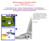
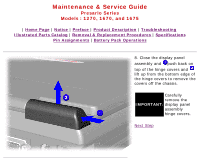
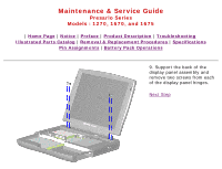
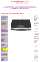
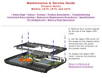
Maintenance & Service Guide Presario Series Models: 1270, 1670, and 1675 | Home Page | Notice | Preface | Product Description | Troubleshooting Illustrated Parts Catalog | Removal & Replacement Procedures | Specifications Pin Assignments | Battery Pack Operations 8. Remove four screws located on the top of the Upper CPU cover. 9. Lift the Upper CPU cover off the snaps on the chassis which will disconnect the power switch from the connector on the system board. To replace the Upper CPU cover, reverse the previous procedures. Return to Removal & Replacement Procedures
-
 1
1 -
2
-
3
-
4
-
5
-
6
-
7
-
8
-
9
-
10
-
11
-
12
-
13
-
14
-
15
-
16
-
17
-
18
-
19
-
20
-
21
-
22
-
23
-
24
-
25
-
26
-
27
-
28
-
29
-
30
-
31
-
32
-
33
-
34
-
35
-
36
-
37
-
38
-
39
-
40
-
41
-
42
-
43
-
44
-
45
-
46
-
47
-
48
-
49
-
50
-
51
-
52
-
53
-
54
-
55
-
56
-
57
-
58
-
 59
59 -
 60
60 -
 61
61 -
 62
62 -
 63
63 -
 64
64 -
 65
65 -
 66
66 -
 67
67 -
 68
68 -
 69
69 -
70
-
71
-
72
-
73
-
74
-
75
-
76
 |
 |

Maintenance & Service Guide
Presario Series
Models: 1270, 1670, and 1675
|
Home Page
|
Notice
|
Preface
|
Product Description
|
Troubleshooting
Illustrated Parts Catalog
|
Removal & Replacement Procedures
|
Specifications
Pin Assignments
|
Battery Pack Operations
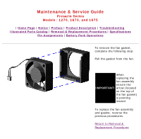
8. Remove four screws located
on the top of the Upper CPU
cover.
9. Lift the Upper CPU cover off
the snaps on the chassis which
will disconnect the power
switch from the connector on
the system board.
To replace the Upper CPU
cover, reverse the previous
procedures.
Return to Removal &
Replacement Procedures