HP Presario 1600 Presario Select 1200 and 1600 Series Maintenance and Service - Page 63
Removing the Upper CPU Cover
 |
View all HP Presario 1600 manuals
Add to My Manuals
Save this manual to your list of manuals |
Page 63 highlights
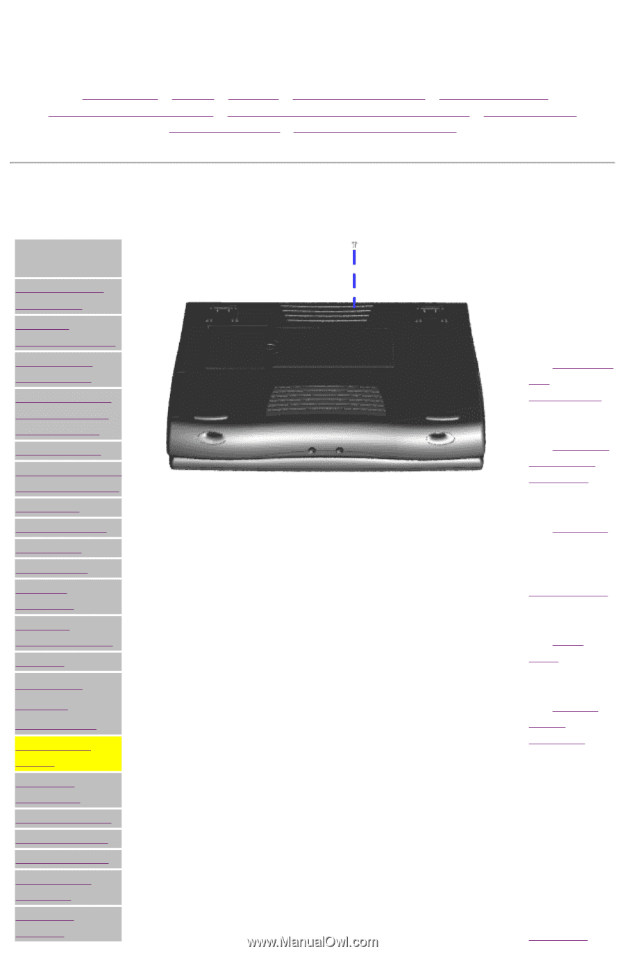
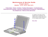
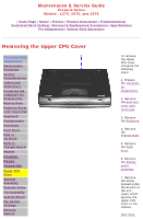
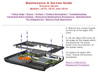
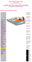
Maintenance & Service Guide Presario Series Models : 1270, 1670, and 1675 | Home Page | Notice | Preface | Product Description | Troubleshooting Illustrated Parts Catalog | Removal & Replacement Procedures | Specifications Pin Assignments | Battery Pack Operations Removing the Upper CPU Cover Disassembly Sequence Electrostatic Discharge Service Considerations Cables and Connectors Preparing the Computer for Disassembly Battery Pack Palmrest Cover with Touch Pad Keyboard Heatspreader Processor Hard Drive DVD or CD Drive Battery Charger Board Modem Display Panel Assembly Upper CPU Cover Speaker Assembly Diskette Drive Fan Assembly System Board Dip Switch Settings Memory Module To remove the Upper CPU cover complete the following steps: 1. Prepare the computer for disassembly. 2. Remove the palmrest cover with touch pad. 3. Remove the keyboard. 4. Remove the heatspreader. 5. Remove the hard drive. 6. Remove the display panel assembly. 7. Remove the screw located under the bottom of the unit (rear) which secures the Upper CPU cover to the chassis. Next Step
-
 1
1 -
2
-
3
-
4
-
5
-
6
-
7
-
8
-
9
-
10
-
11
-
12
-
13
-
14
-
15
-
16
-
17
-
18
-
19
-
20
-
21
-
22
-
23
-
24
-
25
-
26
-
27
-
28
-
29
-
30
-
31
-
32
-
33
-
34
-
35
-
36
-
37
-
38
-
39
-
40
-
41
-
42
-
43
-
44
-
45
-
46
-
47
-
48
-
49
-
50
-
51
-
52
-
53
-
54
-
55
-
56
-
57
-
 58
58 -
 59
59 -
 60
60 -
 61
61 -
 62
62 -
 63
63 -
 64
64 -
 65
65 -
 66
66 -
 67
67 -
 68
68 -
69
-
70
-
71
-
72
-
73
-
74
-
75
-
76
 |
 |