HP Presario 1600 Presario Select 1200 and 1600 Series Maintenance and Service - Page 9
Connector Pin Assignments
 |
View all HP Presario 1600 manuals
Add to My Manuals
Save this manual to your list of manuals |
Page 9 highlights
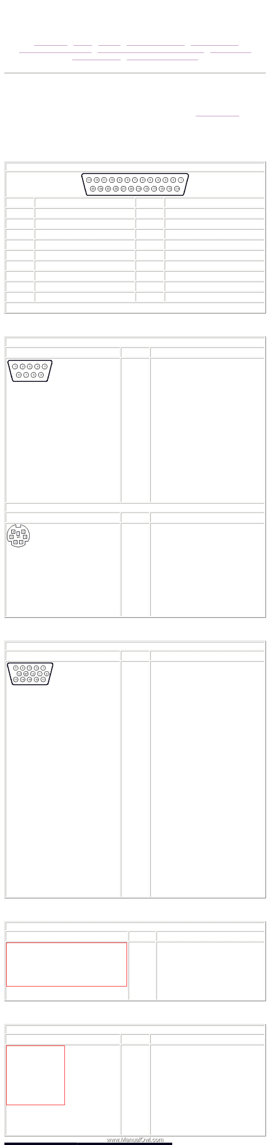
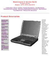
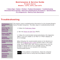
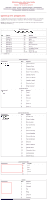
Maintenance & Service Guide Presario Series Models : 1270, 1670, and 1675 | Home Page | Notice | Preface | Product Description | Troubleshooting Illustrated Parts Catalog | Removal & Replacement Procedures | Specifications Pin Assignments | Battery Pack Operations Connector Pin Assignments This appendix provides connector pin assignment tables for Compaq Presario Series Portable Computers. For more information on connectors, refer to the section on Rear Connectors. NOTE: The signals in all tables of this appendix are considered active high unless otherwise indicated by an asterisk (*). Parallel Connector Pin Signal 1 Strobe* 2 Data Bit 0 3 Data Bit 1 4 Data Bit 2 5 Data Bit 3 6 Data Bit 4 7 Data Bit 5 8 Data Bit 6 9 Data Bit 7 * = Active low Connector Connector Pin 10 11 12 13 14 15 16 17 18-25 Signal Acknowledge* Busy Paper Out Select Auto Linefeed* Error* Initialize Printer* Select In* Signal Ground Serial Connector Pin Signal 1 Carrier Detect 2 Receive Data 3 Transmit Data 4 Data Terminal Ready 5 Signal Ground 6 Data Set Ready 7 Ready to Send 8 Clear to Send 9 Ring Indicator Keyboard/Mouse Pin Signal 1 Data 1 2 Data 2 3 Ground 4 +5 V 5 Clock 1 6 Clock 2 Connector External VGA Monitor Pin Signal 1 Red Analog 2 Green Analog 3 Blue Analog 4 Not connected 5 Ground 6 Ground Analog 7 Ground Analog 8 Ground Analog 9 Not connected 10 Ground 11 Monitor Detect 12 DDC2B Data 13 Horizontal Sync 14 Vertical Sync 15 DDC2B Clock Connector Universal Serial Bus Connector Universal Serial Bus Pin Signal 1 +5V Data - 2 Data + 3 Ground 4 Connector Modem Connector Modem Pin Signal 1 Unused 2 Unused 3 Tip 4 Ring 5 Unused 6 Unused
-
 1
1 -
2
-
3
-
 4
4 -
 5
5 -
 6
6 -
 7
7 -
 8
8 -
 9
9 -
 10
10 -
 11
11 -
 12
12 -
 13
13 -
 14
14 -
15
-
16
-
17
-
18
-
19
-
20
-
21
-
22
-
23
-
24
-
25
-
26
-
27
-
28
-
29
-
30
-
31
-
32
-
33
-
34
-
35
-
36
-
37
-
38
-
39
-
40
-
41
-
42
-
43
-
44
-
45
-
46
-
47
-
48
-
49
-
50
-
51
-
52
-
53
-
54
-
55
-
56
-
57
-
58
-
59
-
60
-
61
-
62
-
63
-
64
-
65
-
66
-
67
-
68
-
69
-
70
-
71
-
72
-
73
-
74
-
75
-
76
 |
 |