HP Presario 1600 Presario Select 1200 and 1600 Series Maintenance and Service - Page 48
Return to Removal & Replacement Procedures
 |
View all HP Presario 1600 manuals
Add to My Manuals
Save this manual to your list of manuals |
Page 48 highlights
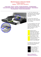
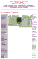
Maintenance & Service Guide Presario Series Models : 1270, 1670, and 1675 | Home Page | Notice | Preface | Product Description | Troubleshooting Illustrated Parts Catalog | Removal & Replacement Procedures | Specifications Pin Assignments | Battery Pack Operations To replace the processor complete the following steps: The notch on the upper left corner of the processor serves as an orientation IMPORTANT: indicator. Align the notch on the left corner of the processor with the notch on the left corner of the processor chassis slot. 1. Insert the processor into the slot on the system board. When installing the processor into the chassis slot, be sure that the hole pattern on the NOTE: chassis slot lines up with the pins on the processor. The processor should drop into the socket without any force. 2. Insert a small blade screw driver into the top slot opening on the processor and push away from the display to lock the processor. Return to Removal & Replacement Procedures
-
 1
1 -
2
-
3
-
4
-
5
-
6
-
7
-
8
-
9
-
10
-
11
-
12
-
13
-
14
-
15
-
16
-
17
-
18
-
19
-
20
-
21
-
22
-
23
-
24
-
25
-
26
-
27
-
28
-
29
-
30
-
31
-
32
-
33
-
34
-
35
-
36
-
37
-
38
-
39
-
40
-
41
-
42
-
 43
43 -
 44
44 -
 45
45 -
 46
46 -
 47
47 -
 48
48 -
 49
49 -
 50
50 -
 51
51 -
 52
52 -
 53
53 -
54
-
55
-
56
-
57
-
58
-
59
-
60
-
61
-
62
-
63
-
64
-
65
-
66
-
67
-
68
-
69
-
70
-
71
-
72
-
73
-
74
-
75
-
76
 |
 |