HP Presario C700 HP G7000 Notebook PC and Compaq Presario C700 Notebook PC - M - Page 61
Switch cover, that secure the switch cover to the computer.
 |
View all HP Presario C700 manuals
Add to My Manuals
Save this manual to your list of manuals |
Page 61 highlights
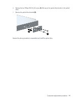
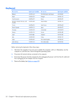
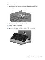
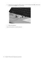
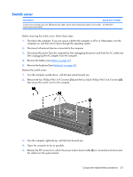
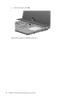
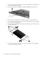
Switch cover Description Spare part number Switch cover (includes caps lock LED board and cable, power button board and cable, and wireless 454940-001 button board and cable) Before removing the switch cover, follow these steps: 1. Shut down the computer. If you are unsure whether the computer is off or in Hibernation, turn the computer on, and then shut it down through the operating system. 2. Disconnect all external devices connected to the computer. 3. Disconnect the power from the computer by first unplugging the power cord from the AC outlet and then unplugging the AC adapter from the computer. 4. Remove the battery (see Battery on page 40). 5. Remove the keyboard (see Keyboard on page 50). Remove the switch cover: 1. Turn the computer upside down, with the rear panel toward you. 2. Remove the four Phillips PM2.5×9.0 screws (1) and the four black Phillips PM2.5×4.0 screws (2) that secure the switch cover to the computer. 3. Turn the computer right-side up, with the front toward you. 4. Open the computer as far as possible. 5. Release the ZIF connector to which the power button board cable (1) is connected and disconnect the cable from the system board. Component replacement procedures 53
-
 1
1 -
2
-
3
-
4
-
5
-
6
-
7
-
8
-
9
-
10
-
11
-
12
-
13
-
14
-
15
-
16
-
17
-
18
-
19
-
20
-
21
-
22
-
23
-
24
-
25
-
26
-
27
-
28
-
29
-
30
-
31
-
32
-
33
-
34
-
35
-
36
-
37
-
38
-
39
-
40
-
41
-
42
-
43
-
44
-
45
-
46
-
47
-
48
-
49
-
50
-
51
-
52
-
53
-
54
-
55
-
 56
56 -
 57
57 -
 58
58 -
 59
59 -
 60
60 -
 61
61 -
 62
62 -
 63
63 -
 64
64 -
 65
65 -
 66
66 -
67
-
68
-
69
-
70
-
71
-
72
-
73
-
74
-
75
-
76
-
77
-
78
-
79
-
80
-
81
-
82
-
83
-
84
-
85
-
86
-
87
-
88
-
89
-
90
-
91
-
92
-
93
-
94
-
95
-
96
-
97
-
98
-
99
-
100
-
101
-
102
-
103
-
104
-
105
-
106
-
107
-
108
-
109
-
110
-
111
-
112
-
113
-
114
-
115
-
116
-
117
-
118
-
119
-
120
-
121
-
122
-
123
-
124
-
125
-
126
-
127
-
128
-
129
-
130
-
131
-
132
-
133
-
134
-
135
-
136
-
137
-
138
-
139
 |
 |