HP Presario C700 HP G7000 Notebook PC and Compaq Presario C700 Notebook PC - M - Page 71
from on the system board.
 |
View all HP Presario C700 manuals
Add to My Manuals
Save this manual to your list of manuals |
Page 71 highlights
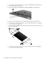
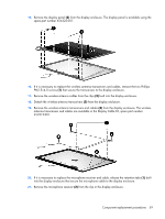
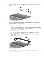
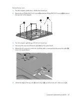
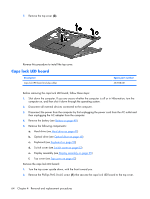
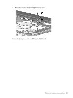
Remove the top cover: 1. Turn the computer upside down, with the front toward you. 2. Remove the two Phillips PM2.5×4.0 screws (1) and the ten Phillips PM2.5×9.0 screws (2) that secure the top cover to the computer. 3. Turn the computer right-side up, with the front toward you. 4. Disconnect the caps lock LED board cable (1) from the system board. 5. Release the ZIF connector to which the TouchPad cable is connected and disconnect the cable (2) from on the system board. 6. Lift the rear edge of the top cover (1) and swing it (2) up and forward until it rests at an angle. Component replacement procedures 63
-
 1
1 -
2
-
3
-
4
-
5
-
6
-
7
-
8
-
9
-
10
-
11
-
12
-
13
-
14
-
15
-
16
-
17
-
18
-
19
-
20
-
21
-
22
-
23
-
24
-
25
-
26
-
27
-
28
-
29
-
30
-
31
-
32
-
33
-
34
-
35
-
36
-
37
-
38
-
39
-
40
-
41
-
42
-
43
-
44
-
45
-
46
-
47
-
48
-
49
-
50
-
51
-
52
-
53
-
54
-
55
-
56
-
57
-
58
-
59
-
60
-
61
-
62
-
63
-
64
-
65
-
 66
66 -
 67
67 -
 68
68 -
 69
69 -
 70
70 -
 71
71 -
 72
72 -
 73
73 -
 74
74 -
 75
75 -
 76
76 -
77
-
78
-
79
-
80
-
81
-
82
-
83
-
84
-
85
-
86
-
87
-
88
-
89
-
90
-
91
-
92
-
93
-
94
-
95
-
96
-
97
-
98
-
99
-
100
-
101
-
102
-
103
-
104
-
105
-
106
-
107
-
108
-
109
-
110
-
111
-
112
-
113
-
114
-
115
-
116
-
117
-
118
-
119
-
120
-
121
-
122
-
123
-
124
-
125
-
126
-
127
-
128
-
129
-
130
-
131
-
132
-
133
-
134
-
135
-
136
-
137
-
138
-
139
 |
 |
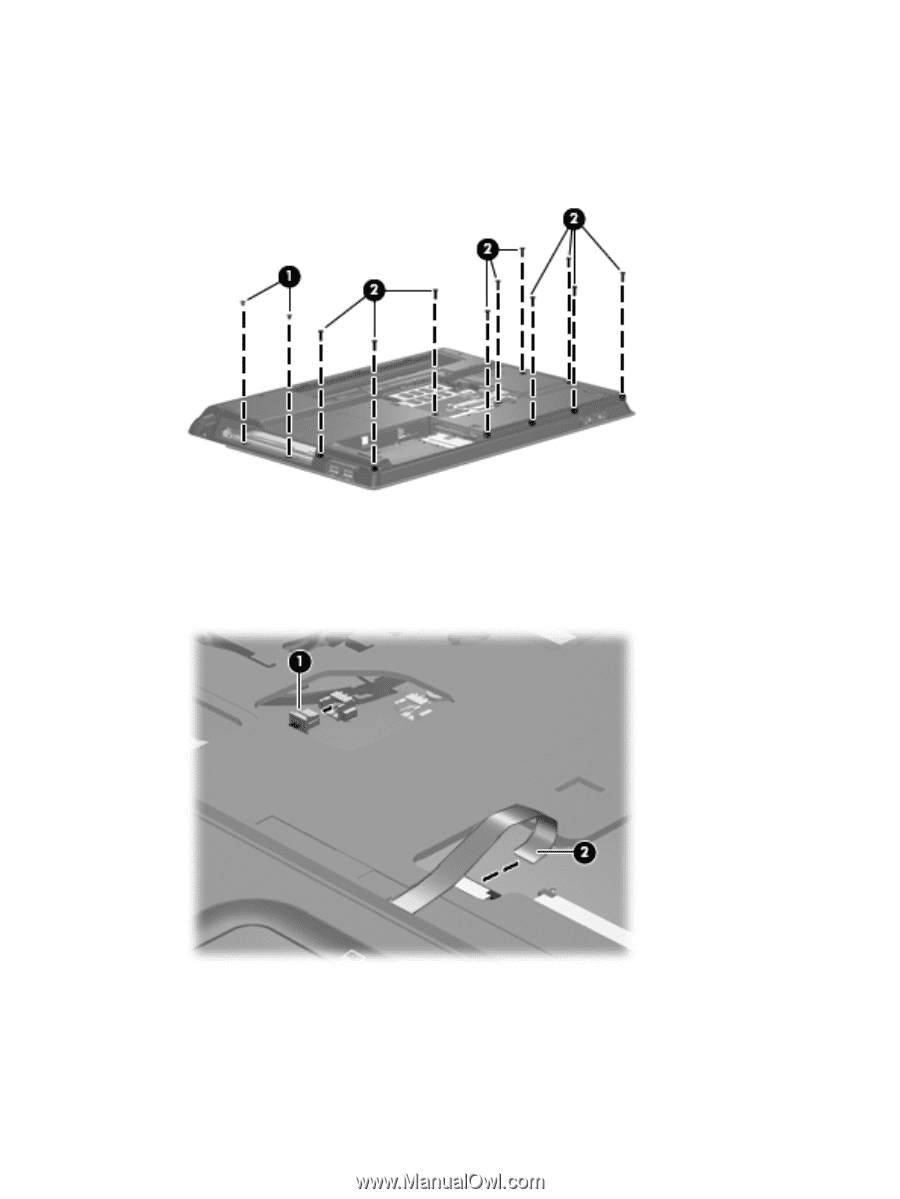
Remove the top cover:
1
.
Turn the computer upside down, with the front toward you.
2
.
Remove the two Phillips PM2.5×4.0 screws
(1)
and the ten Phillips PM2.5×9.0 screws
(2)
that secure
the top cover to the computer.
3
.
Turn the computer right-side up, with the front toward you.
4
.
Disconnect the caps lock LED board cable
(1)
from the system board.
5
.
Release the ZIF connector to which the TouchPad cable is connected and disconnect the cable
(2)
from on the system board.
6
.
Lift the rear edge of the top cover
(1)
and swing it
(2)
up and forward until it rests at an angle.
Component replacement procedures
63