HP Presario C700 HP G7000 Notebook PC and Compaq Presario C700 Notebook PC - M - Page 64
that secure the display assembly to the, Remove the display assembly
 |
View all HP Presario C700 manuals
Add to My Manuals
Save this manual to your list of manuals |
Page 64 highlights
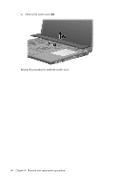
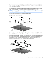
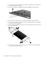
3. Remove the microphone cable and the WLAN antenna cables from the clips (4) and routing channel built into the top cover. CAUTION: The display assembly will be unsupported when the following screws are removed. To prevent damage to the display assembly, support it before removing the screws. 4. Remove the four black Phillips PM2.5×9.0 screws (1) that secure the display assembly to the computer. 5. Remove the display assembly (2). 56 Chapter 4 Removal and replacement procedures
-
 1
1 -
2
-
3
-
4
-
5
-
6
-
7
-
8
-
9
-
10
-
11
-
12
-
13
-
14
-
15
-
16
-
17
-
18
-
19
-
20
-
21
-
22
-
23
-
24
-
25
-
26
-
27
-
28
-
29
-
30
-
31
-
32
-
33
-
34
-
35
-
36
-
37
-
38
-
39
-
40
-
41
-
42
-
43
-
44
-
45
-
46
-
47
-
48
-
49
-
50
-
51
-
52
-
53
-
54
-
55
-
56
-
57
-
58
-
 59
59 -
 60
60 -
 61
61 -
 62
62 -
 63
63 -
 64
64 -
 65
65 -
 66
66 -
 67
67 -
 68
68 -
 69
69 -
70
-
71
-
72
-
73
-
74
-
75
-
76
-
77
-
78
-
79
-
80
-
81
-
82
-
83
-
84
-
85
-
86
-
87
-
88
-
89
-
90
-
91
-
92
-
93
-
94
-
95
-
96
-
97
-
98
-
99
-
100
-
101
-
102
-
103
-
104
-
105
-
106
-
107
-
108
-
109
-
110
-
111
-
112
-
113
-
114
-
115
-
116
-
117
-
118
-
119
-
120
-
121
-
122
-
123
-
124
-
125
-
126
-
127
-
128
-
129
-
130
-
131
-
132
-
133
-
134
-
135
-
136
-
137
-
138
-
139
 |
 |

3
.
Remove the microphone cable and the WLAN antenna cables from the clips
(4)
and routing channel
built into the top cover.
CAUTION:
The display assembly will be unsupported when the following screws are removed. To
prevent damage to the display assembly, support it before removing the screws.
4
.
Remove the four black Phillips PM2.5×9.0 screws
(1)
that secure the display assembly to the
computer.
5
.
Remove the display assembly
(2)
.
56
Chapter
4
Removal and replacement procedures