HP Presario C700 HP G7000 Notebook PC and Compaq Presario C700 Notebook PC - M - Page 65
Eight Phillips PM2.5×7.0 screws., bezel until the bezel disengages from the display enclosure.
 |
View all HP Presario C700 manuals
Add to My Manuals
Save this manual to your list of manuals |
Page 65 highlights
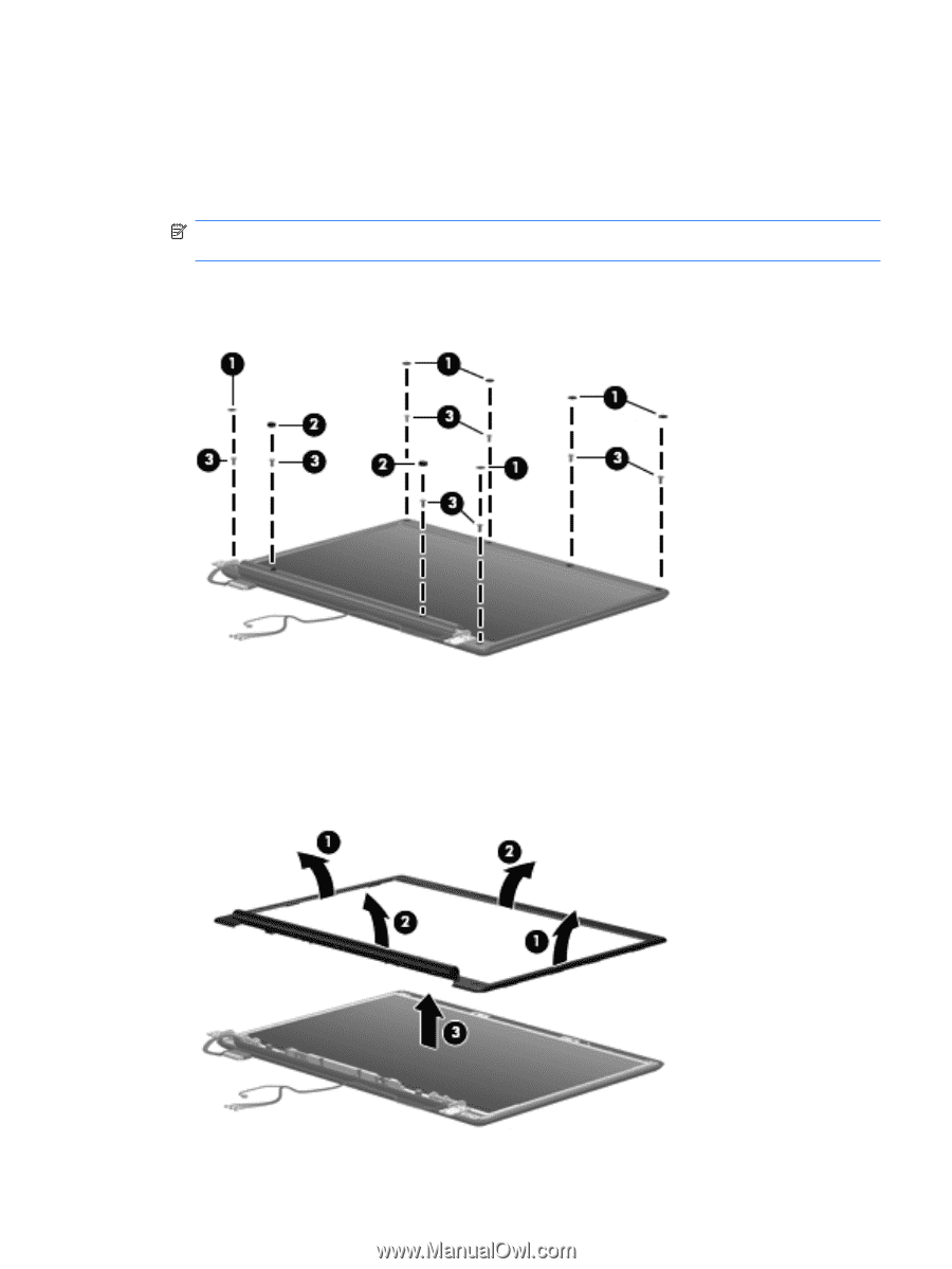
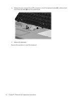
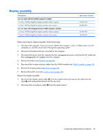
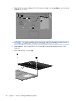
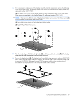
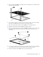
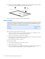
6. If it is necessary to replace any of the display assembly internal components, remove the following screw covers and screws. The display rubber screw covers are included in the Display Rubber Kit, spare part number 454917-001. (1) Six rubber screw covers on the display bezel top edge and bottom edge corners. The rubber screw covers are available in the Display Rubber Kit, spare part number 454917-001. NOTE: There are two different sizes of display bezel rubber screw covers. The thicker covers (2) must be installed in the bottom center screw holes. (2) Two rubber screw covers on the display bezel bottom edge. (3) Eight Phillips PM2.5×7.0 screws. 7. Flex the inside edges of the left and right sides (1) and the top and bottom sides (2) of the display bezel until the bezel disengages from the display enclosure. 8. Remove the display bezel (3). The display bezel is available using spare part numbers 454909-001 (HP G7000 computer models without a camera), 462445-001 (HP G7000 computer models with a camera, 454910-001 (Compaq Presario C700 computer models without a camera), and 462446-001 (Compaq Presario C700 computer models with a camera). Component replacement procedures 57
-
 1
1 -
2
-
3
-
4
-
5
-
6
-
7
-
8
-
9
-
10
-
11
-
12
-
13
-
14
-
15
-
16
-
17
-
18
-
19
-
20
-
21
-
22
-
23
-
24
-
25
-
26
-
27
-
28
-
29
-
30
-
31
-
32
-
33
-
34
-
35
-
36
-
37
-
38
-
39
-
40
-
41
-
42
-
43
-
44
-
45
-
46
-
47
-
48
-
49
-
50
-
51
-
52
-
53
-
54
-
55
-
56
-
57
-
58
-
59
-
 60
60 -
 61
61 -
 62
62 -
 63
63 -
 64
64 -
 65
65 -
 66
66 -
 67
67 -
 68
68 -
 69
69 -
 70
70 -
71
-
72
-
73
-
74
-
75
-
76
-
77
-
78
-
79
-
80
-
81
-
82
-
83
-
84
-
85
-
86
-
87
-
88
-
89
-
90
-
91
-
92
-
93
-
94
-
95
-
96
-
97
-
98
-
99
-
100
-
101
-
102
-
103
-
104
-
105
-
106
-
107
-
108
-
109
-
110
-
111
-
112
-
113
-
114
-
115
-
116
-
117
-
118
-
119
-
120
-
121
-
122
-
123
-
124
-
125
-
126
-
127
-
128
-
129
-
130
-
131
-
132
-
133
-
134
-
135
-
136
-
137
-
138
-
139
 |
 |