HP ProBook 4340s HP ProBook 4340s Notebook PC HP ProBook 4341s Notebook PC - M - Page 69
System board, the computer on, and then shut it down through the operating system.
 |
View all HP ProBook 4340s manuals
Add to My Manuals
Save this manual to your list of manuals |
Page 69 highlights
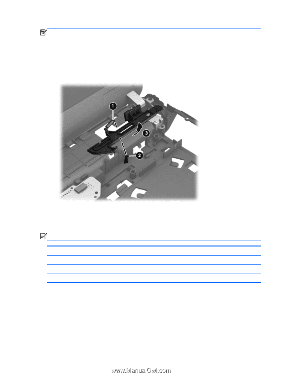
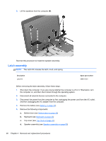
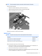
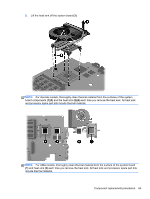
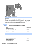
NOTE: The latch assembly includes a small spring. Note the location of the spring. Remove the latch assembly: 1. Position the computer right-side up, with the front toward you. 2. Detach the spring hook (1) from the tab on the base enclosure (2). 3. Rotate the latch (3) and lift it from the computer. Reverse this procedure to install the latch assembly. System board NOTE: All system board spare part kits include replacement thermal material. Description System board for use in models with discrete graphics System board for use in models with UMA graphics System board for use in Japan in models with UMA graphics Spare part number 683855-001 683856-001 696335-001 Before removing the system board, follow these steps: 1. Shut down the computer. If you are unsure whether the computer is off or in Hibernation, turn the computer on, and then shut it down through the operating system. 2. Disconnect all external devices connected to the computer. 3. Disconnect the power from the computer by first unplugging the power cord from the AC outlet, and then unplugging the AC adapter from the computer. Component replacement procedures 61
-
 1
1 -
2
-
3
-
4
-
5
-
6
-
7
-
8
-
9
-
10
-
11
-
12
-
13
-
14
-
15
-
16
-
17
-
18
-
19
-
20
-
21
-
22
-
23
-
24
-
25
-
26
-
27
-
28
-
29
-
30
-
31
-
32
-
33
-
34
-
35
-
36
-
37
-
38
-
39
-
40
-
41
-
42
-
43
-
44
-
45
-
46
-
47
-
48
-
49
-
50
-
51
-
52
-
53
-
54
-
55
-
56
-
57
-
58
-
59
-
60
-
61
-
62
-
63
-
 64
64 -
 65
65 -
 66
66 -
 67
67 -
 68
68 -
 69
69 -
 70
70 -
 71
71 -
 72
72 -
 73
73 -
 74
74 -
75
-
76
-
77
-
78
-
79
-
80
-
81
-
82
-
83
-
84
-
85
-
86
-
87
-
88
-
89
-
90
-
91
-
92
-
93
-
94
-
95
-
96
-
97
-
98
-
99
-
100
-
101
-
102
-
103
-
104
-
105
-
106
-
107
-
108
-
109
-
110
-
111
-
112
-
113
-
114
-
115
-
116
-
117
 |
 |