HP ProBook 4340s HP ProBook 4340s Notebook PC HP ProBook 4341s Notebook PC - M - Page 70
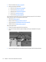
Remove the Phillips PM2.5×6.0 screw, Remove the system board
 |
View all HP ProBook 4340s manuals
Add to My Manuals
Save this manual to your list of manuals |
Page 70 highlights
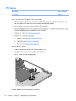
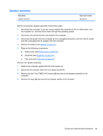
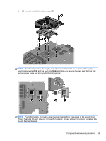
4. Remove the battery (see Battery on page 31). 5. Remove the following components: a. Bottom door (see Bottom door on page 33). b. Hard drive (see Hard drive on page 37) c. Optical drive (see Optical drive on page 35) d. Keyboard (see Keyboard on page 45) e. Top cover (see Top cover on page 47) When replacing the system board, be sure to remove the following components from the defective system board and install on the replacement system board: ● SIM card (see SIM on page 34) ● Memory module (see Memory modules on page 39) ● WLAN module (see WLAN/Bluetooth combo card on page 43) ● WWAN module (see WWAN module on page 41) Remove the system board: 1. Position the computer upright with the front toward you. 2. Disconnect the display cable (1), speaker cable (2), and the power cable (3) from the system board. 3. Remove the Phillips PM2.5×6.0 screw (1) that secures the system board to the base enclosure. 62 Chapter 4 Removal and replacement procedures
-
 1
1 -
2
-
3
-
4
-
5
-
6
-
7
-
8
-
9
-
10
-
11
-
12
-
13
-
14
-
15
-
16
-
17
-
18
-
19
-
20
-
21
-
22
-
23
-
24
-
25
-
26
-
27
-
28
-
29
-
30
-
31
-
32
-
33
-
34
-
35
-
36
-
37
-
38
-
39
-
40
-
41
-
42
-
43
-
44
-
45
-
46
-
47
-
48
-
49
-
50
-
51
-
52
-
53
-
54
-
55
-
56
-
57
-
58
-
59
-
60
-
61
-
62
-
63
-
64
-
 65
65 -
 66
66 -
 67
67 -
 68
68 -
 69
69 -
 70
70 -
 71
71 -
 72
72 -
 73
73 -
 74
74 -
 75
75 -
76
-
77
-
78
-
79
-
80
-
81
-
82
-
83
-
84
-
85
-
86
-
87
-
88
-
89
-
90
-
91
-
92
-
93
-
94
-
95
-
96
-
97
-
98
-
99
-
100
-
101
-
102
-
103
-
104
-
105
-
106
-
107
-
108
-
109
-
110
-
111
-
112
-
113
-
114
-
115
-
116
-
117
 |
 |