HP ProBook 4340s HP ProBook 4340s Notebook PC HP ProBook 4341s Notebook PC - M - Page 71
Heat sink, Remove the battery see
 |
View all HP ProBook 4340s manuals
Add to My Manuals
Save this manual to your list of manuals |
Page 71 highlights
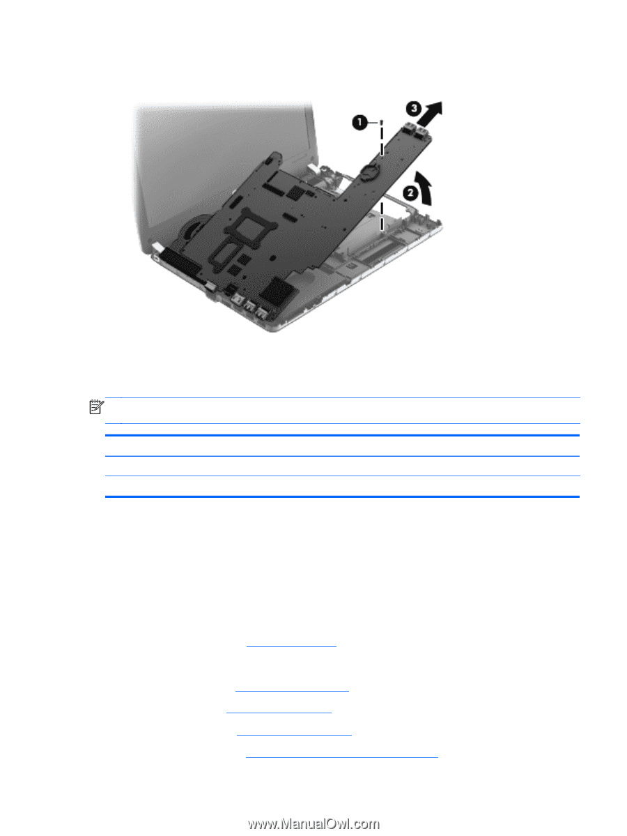
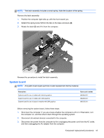
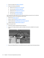
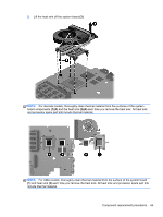
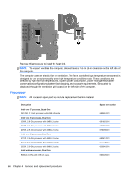
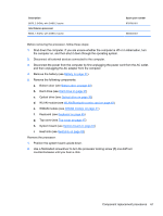
4. Lift the right side of the system board up at an angle (2), and then lift the system board up and to the right to remove it (3). Reverse this procedure to install the system board. Heat sink NOTE: The fan and heat sink are combined into one assembly. All fan/heat sink spare part kits contain replacement thermal material. Description Heat sink for use in computers with discrete graphics Heat sink for use in computers with UMA graphics Spare part number 683860-001 683861-001 Before removing the heat sink, follow these steps: 1. Shut down the computer. If you are unsure whether the computer is off or in Hibernation, turn the computer on, and then shut it down through the operating system. 2. Disconnect all external devices connected to the computer. 3. Disconnect the power from the computer by first unplugging the power cord from the AC outlet, and then unplugging the AC adapter from the computer. 4. Remove the battery (see Battery on page 31). 5. Remove the following components: a. Bottom door (see Bottom door on page 33). b. Hard drive (see Hard drive on page 37) c. Optical drive (see Optical drive on page 35) d. WLAN module (see WLAN/Bluetooth combo card on page 43) Component replacement procedures 63
-
 1
1 -
2
-
3
-
4
-
5
-
6
-
7
-
8
-
9
-
10
-
11
-
12
-
13
-
14
-
15
-
16
-
17
-
18
-
19
-
20
-
21
-
22
-
23
-
24
-
25
-
26
-
27
-
28
-
29
-
30
-
31
-
32
-
33
-
34
-
35
-
36
-
37
-
38
-
39
-
40
-
41
-
42
-
43
-
44
-
45
-
46
-
47
-
48
-
49
-
50
-
51
-
52
-
53
-
54
-
55
-
56
-
57
-
58
-
59
-
60
-
61
-
62
-
63
-
64
-
65
-
 66
66 -
 67
67 -
 68
68 -
 69
69 -
 70
70 -
 71
71 -
 72
72 -
 73
73 -
 74
74 -
 75
75 -
 76
76 -
77
-
78
-
79
-
80
-
81
-
82
-
83
-
84
-
85
-
86
-
87
-
88
-
89
-
90
-
91
-
92
-
93
-
94
-
95
-
96
-
97
-
98
-
99
-
100
-
101
-
102
-
103
-
104
-
105
-
106
-
107
-
108
-
109
-
110
-
111
-
112
-
113
-
114
-
115
-
116
-
117
 |
 |