HP ProBook 6540b HP ProBook 6545b, 6540b, 6445b and 6440b Notebook PC - Mainte - Page 117
Disconnect the webcam module cable
 |
View all HP ProBook 6540b manuals
Add to My Manuals
Save this manual to your list of manuals |
Page 117 highlights
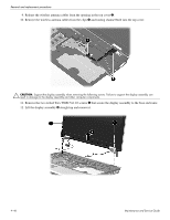
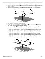
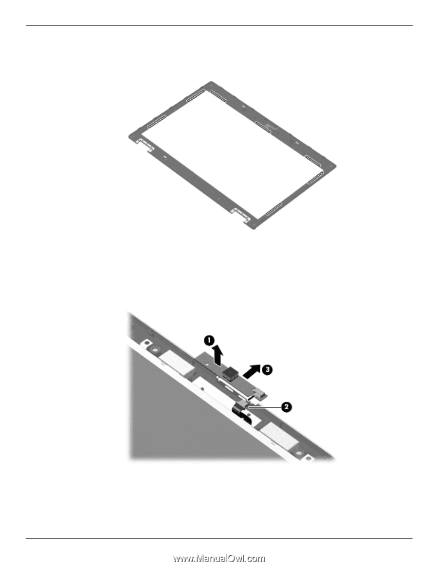
Removal and replacement procedures ✎ When installing the display bezel, it may be necessary to replace the double-sided tape that secures the bezel to the display enclosure. The tape should be installed in the locations shown in the following illustration. 14. If it is necessary to replace the webcam module: a. Release the webcam module 1 as far from the display enclosure as the webcam module cable allows. (The webcam module is attached to the display enclosure with double-sided tape.) b. Disconnect the webcam module cable 2 from the webcam module. c. Remove the webcam module 3. The webcam module is available using spare part number 583219-001. 4-48 Maintenance and Service Guide
-
 1
1 -
2
-
3
-
4
-
5
-
6
-
7
-
8
-
9
-
10
-
11
-
12
-
13
-
14
-
15
-
16
-
17
-
18
-
19
-
20
-
21
-
22
-
23
-
24
-
25
-
26
-
27
-
28
-
29
-
30
-
31
-
32
-
33
-
34
-
35
-
36
-
37
-
38
-
39
-
40
-
41
-
42
-
43
-
44
-
45
-
46
-
47
-
48
-
49
-
50
-
51
-
52
-
53
-
54
-
55
-
56
-
57
-
58
-
59
-
60
-
61
-
62
-
63
-
64
-
65
-
66
-
67
-
68
-
69
-
70
-
71
-
72
-
73
-
74
-
75
-
76
-
77
-
78
-
79
-
80
-
81
-
82
-
83
-
84
-
85
-
86
-
87
-
88
-
89
-
90
-
91
-
92
-
93
-
94
-
95
-
96
-
97
-
98
-
99
-
100
-
101
-
102
-
103
-
104
-
105
-
106
-
107
-
108
-
109
-
110
-
111
-
 112
112 -
 113
113 -
 114
114 -
 115
115 -
 116
116 -
 117
117 -
 118
118 -
 119
119 -
 120
120 -
 121
121 -
 122
122 -
123
-
124
-
125
-
126
-
127
-
128
-
129
-
130
-
131
-
132
-
133
-
134
-
135
-
136
-
137
-
138
-
139
-
140
-
141
-
142
-
143
-
144
-
145
-
146
-
147
-
148
-
149
-
150
-
151
-
152
-
153
-
154
-
155
-
156
-
157
-
158
-
159
-
160
-
161
-
162
-
163
-
164
-
165
-
166
-
167
-
168
-
169
-
170
-
171
-
172
-
173
-
174
-
175
-
176
-
177
-
178
-
179
-
180
-
181
-
182
-
183
-
184
-
185
-
186
-
187
-
188
-
189
-
190
-
191
-
192
-
193
-
194
-
195
-
196
-
197
-
198
-
199
-
200
-
201
-
202
-
203
-
204
-
205
-
206
-
207
-
208
-
209
-
210
-
211
-
212
-
213
-
214
-
215
-
216
-
217
-
218
-
219
-
220
-
221
 |
 |
4–48
Maintenance and Service Guide
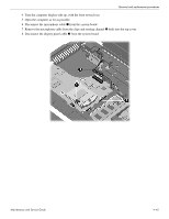
Removal and replacement procedures
✎
When installing the display bezel, it may be necessary to replace the double-sided tape that secures
the bezel to the display enclosure. The tape should be installed in the locations shown in the
following illustration.
14. If it is necessary to replace the webcam module:
a.
Release the webcam module
1
as far from the display enclosure as the webcam module cable allows.
(The webcam module is attached to the display enclosure with double-sided tape.)
b.
Disconnect the webcam module cable
2
from the webcam module.
c.
Remove the webcam module
3
. The webcam module is available using spare part number 583219-001.