HP ProLiant BL420c HP ProLiant BL420c Gen8 Server Blade User Guide - Page 34
Lockstep Memory population guidelines, Population order, Installing a DIMM
 |
View all HP ProLiant BL420c manuals
Add to My Manuals
Save this manual to your list of manuals |
Page 34 highlights
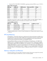
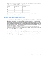
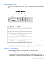
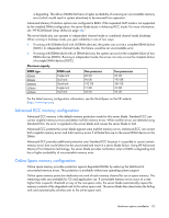
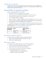
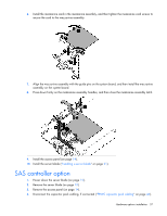
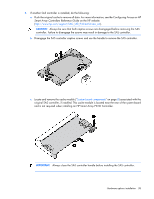
Lockstep Memory population guidelines For Lockstep memory mode configurations, observe the following guidelines: • Observe the general DIMM slot population guidelines (on page 33). • Always install DIMMs in channel 2 and 3 for each installed processor. • Do not install DIMMs in channel 1 for any processor. • DIMM configuration on channel 2 and channel 3 of a processor must be identical. • In multi-processor configurations, each processor must have a valid Lockstep Memory mode configuration. • In multi-processor configurations, each processor may have a different valid Lockstep Memory mode configuration. Population order For memory configurations with a single processor or multiple processors, populate the DIMM slots in the following order: • LRDIMM: Sequentially in alphabetical order (A through F) • RDIMM: Sequentially in alphabetical order (A through F) • UDIMM: A through C, sequentially in alphabetical order. Do not populate DIMM slots D through F. After installing the DIMMs, use RBSU to configure Advanced ECC, online spare, or lockstep memory support. Installing a DIMM CAUTION: To avoid damage to the hard drives, memory, and other system components, the air baffle, drive blanks, and access panel must be installed when the server is powered up. 1. Power down the server blade (on page 12). 2. Remove the server blade (on page 13). 3. Remove the access panel (on page 14). 4. Disconnect the capacitor pack cabling, if connected ("FBWC capacitor pack cabling" on page 46). 5. Remove the SAS controller (on page 14). 6. Remove all DIMM baffles ("Remove the DIMM baffle" on page 16). 7. Locate the DIMM tool ("Tool locations" on page 10) and remove it from the DIMM baffle. 8. Use the DIMM tool to open the DIMM slot. Hardware options installation 34
-
 1
1 -
2
-
3
-
4
-
5
-
6
-
7
-
8
-
9
-
10
-
11
-
12
-
13
-
14
-
15
-
16
-
17
-
18
-
19
-
20
-
21
-
22
-
23
-
24
-
25
-
26
-
27
-
28
-
 29
29 -
 30
30 -
 31
31 -
 32
32 -
 33
33 -
 34
34 -
 35
35 -
 36
36 -
 37
37 -
 38
38 -
 39
39 -
40
-
41
-
42
-
43
-
44
-
45
-
46
-
47
-
48
-
49
-
50
-
51
-
52
-
53
-
54
-
55
-
56
-
57
-
58
-
59
-
60
-
61
-
62
-
63
-
64
-
65
-
66
-
67
-
68
-
69
-
70
-
71
-
72
-
73
-
74
-
75
-
76
-
77
-
78
-
79
-
80
-
81
-
82
-
83
-
84
-
85
-
86
-
87
-
88
 |
 |