HP ProLiant BL490c HP ProLiant BL490c G6 Server Blade User Guide - Page 27
Lockstep Memory population guidelines, Single-processor Lockstep population order
 |
View all HP ProLiant BL490c manuals
Add to My Manuals
Save this manual to your list of manuals |
Page 27 highlights
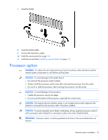
Lockstep Memory population guidelines For Lockstep memory mode configurations, observe the following guidelines: • Observe the general DIMM slot population guidelines (on page 25). • Always install DIMMs in channels 1 and 2 for each installed processor. • Do not install DIMMs in channel 3 for any processor. • DIMM configuration on channel 1 and channel 2 of a processor must be identical. • In multi-processor configurations, each processor must have a valid Lockstep Memory configuration. • In multi-processor configurations, each processor may have a different valid Lockstep Memory configuration. Single-processor Lockstep population order For Lockstep memory mode configurations with a single processor, populate the DIMM slots in the following order: • RDIMM o First: A and B o Next: D and E o Last: G and H o Do not populate slots C, F, or I. • UDIMM o First: A and B o Last: D and E o Do not populate slots C, F, G, H, or I. After installing the DIMMs, use RBSU to configure the system for Lockstep memory support ("Configuring lockstep memory" on page 50). Multi-processor Lockstep population order For Lockstep memory mode configurations with multiple processors, populate the DIMM slots for each processor in the following order: • RDIMM o First: A and B o Next: D and E o Last: G and H o Do not populate slots C, F, or I. • UDIMM o First: A and B o Last: D and E o Do not populate slots C, F, G, H, or I. After installing the DIMMs, use RBSU to configure the system for Lockstep memory support ("Configuring lockstep memory" on page 50). Hardware options installation 27
-
 1
1 -
2
-
3
-
4
-
5
-
6
-
7
-
8
-
9
-
10
-
11
-
12
-
13
-
14
-
15
-
16
-
17
-
18
-
19
-
20
-
21
-
 22
22 -
 23
23 -
 24
24 -
 25
25 -
 26
26 -
 27
27 -
 28
28 -
 29
29 -
 30
30 -
 31
31 -
 32
32 -
33
-
34
-
35
-
36
-
37
-
38
-
39
-
40
-
41
-
42
-
43
-
44
-
45
-
46
-
47
-
48
-
49
-
50
-
51
-
52
-
53
-
54
-
55
-
56
-
57
-
58
-
59
-
60
-
61
-
62
-
63
-
64
-
65
-
66
-
67
-
68
-
69
-
70
-
71
-
72
-
73
-
74
-
75
-
76
-
77
-
78
-
79
-
80
-
81
-
82
-
83
-
84
-
85
-
86
-
87
-
88
-
89
-
90
-
91
-
92
-
93
-
94
-
95
-
96
-
97
-
98
-
99
-
100
-
101
 |
 |